Kia Picanto (JA): Engine Electrical System / Charging System
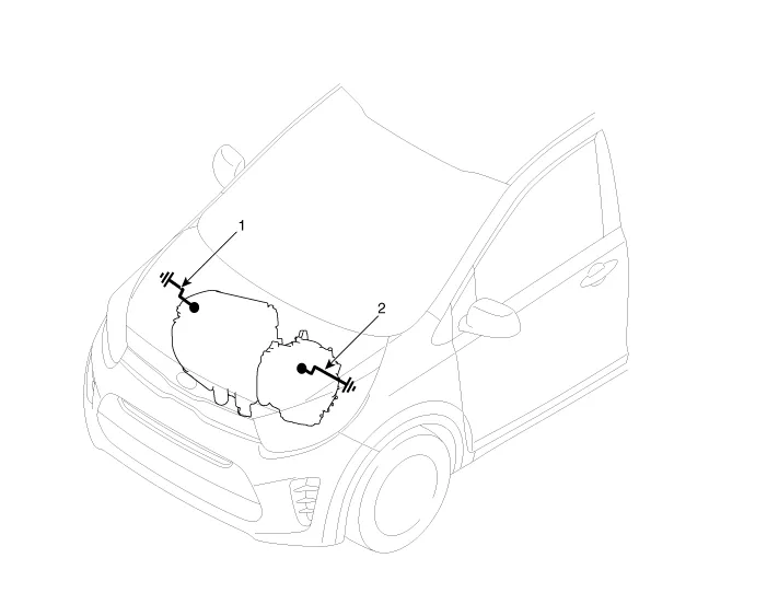
Components and components location
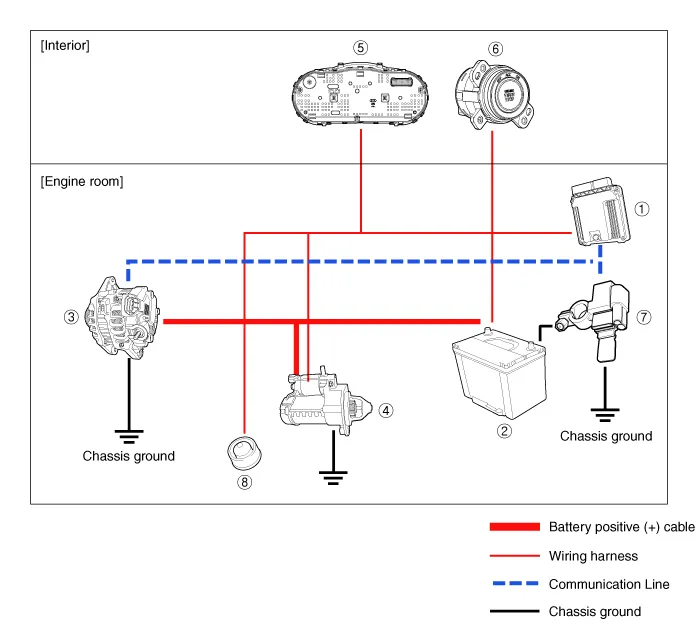
① ECM
② Battery
③ Alternator
④ Starter
⑤ Instrument Cluster
⑥ Ignition switch or start/stop button
⑦ Battery sensor
⑧ Hood switch
Description and operation
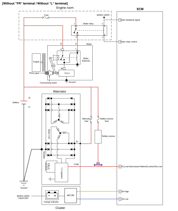
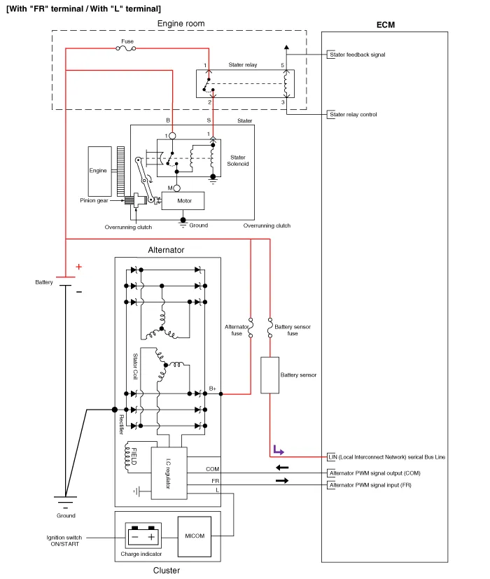
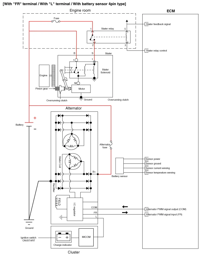
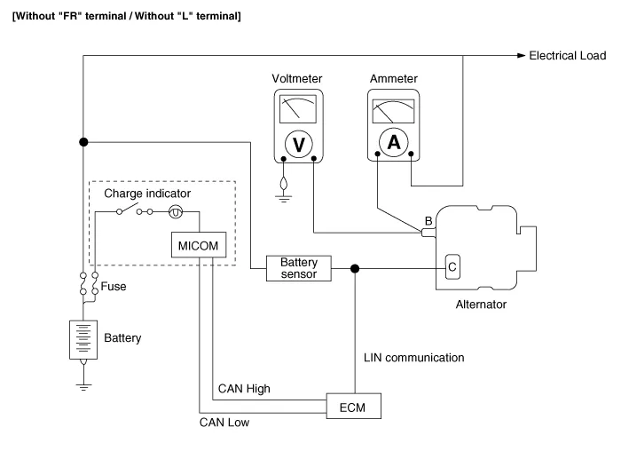
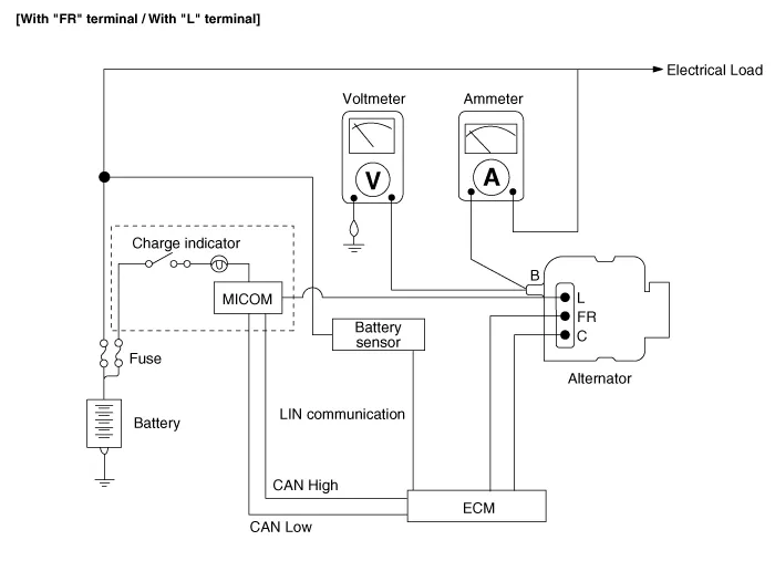
The charging system consists of a battery, an alternator with a built-in regulator, and the charging indicator light and wire.
The Alternator has eight built-in diodes, each rectifying AC current to DC current.
Therefore, DC current appears at alternator "B" terminal.
The charging voltage of this alternator is regulated by the battery
voltage detection system. The main components of the alternator are the
rotor, stator, rectifier, capacitor brushes, bearings and V-ripped belt
pulley. The brush holder contains a built-in electronic voltage
regulator.
Alternator Management System
Alternator
management system controls the charging voltage set point in order to
improve fuel economy, manage alternator load under various operating
conditions, keep the battery charged, and protect the battery from
over-charging. ECM controls generating voltage by duty cycle (charging
control, discharging control, normal control) based on the battery
conditions and vehicle operating conditions.
The
system conducts discharging control when the vehicle accelerates.
Vehicle reduces an alternator load and consumes an electric power from
the battery.
The
system conducts charging control when the vehicle decelerates. Vehicle
increases an alternator load and charges the battery.
Schematic diagrams
Repair procedures
| •
| Battery efficiency inspection |
| •
| Battery voltage inspection |
| •
| Charging voltage insptection |
| •
| Terminal tightening state inspection |
| •
| Engine/ transmission ground state inspection |
| •
| Wiring harness ground state inspection |
| •
| Electrical specification Inspection |
| •
| Vehicle parasitic current inspection |
| •
| Battery capacity inspection |
Battery Efficiency Inspection
| •
| Check that the battery cables are connected to the correct terminals. |
| •
| Disconnect the battery cables when the battery is given a quick charge. |
| •
| Never disconnect the battery while the engine is running. |
| •
| Perform battery test by using the load tester and battery tester. |
|
Battery Voltage Inspection
| 1. | After
having driven the vehicle and in the case that 20 minutes have not
passed after having stopped the engine, turn the ignition switch ON and
turn on the electrical system (headlamp, blower motor, rear defogger
etc.) for 60 seconds to remove the surface charge. |
| 2. | Turn the ignition switch OFF and turn off the electrical systems. |
| 3. | Measure the battery voltage between the negative (-) and positive (+) terminals of the battery.
Standard voltage : Approximately 12.5 - 12.9 V [at 20°C (68°F)] |
If the voltage is less than specification, charge the battery. |
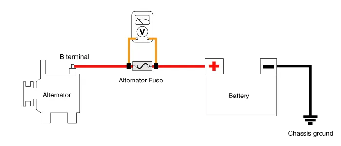
General Inspection
| 1. | Check that the battery terminals are not loose or corroded.
(Refer to Charging System - "Battery")
|
| 2. | Check the fuses for continuity.
Alternator Fuse
| (1) | Check the alternator fuse for continuity.
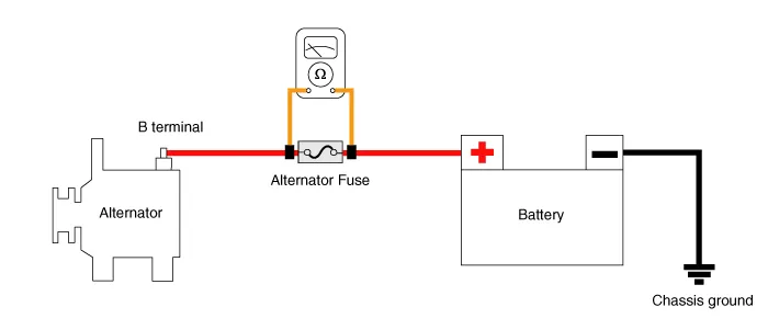 |
| (2) | Measure the voltage as shown in the image below.
Standard value : Approximately 0 V |
 |
| (3) | If the alternator fuse is blown, replace it as in the procedure below: | a. | Turn ignition switch OFF and disconnect the battery negative (-) terminal. |
| b. | Remove the battery positive (+) cable mounting nut.. |
| c. | Replace the nominal alternator fuse or battery cable. |
| d. | Install in the reverse order of removal. |
|
|
| 3. | Inspect the drive belt. | (1) | Visually check the belt for excessive wear, frayed cords, etc. If any defect has been found, replace the drive belt. | •
| Cracks on the rib side of a belt are considered acceptable. If the belt has chunks missing from the ribs, it should be replaced. |
|
 |
|
| 4. | Measure and adjust drive belt tension.
(Refer to Engine Mechanical System - "Drive Belt")
|
| 5. | Visually check alternator wiring and listen for abnormal noises. | (1) | Check that the wiring is in good condition. |
| (2) | Check that there is no abnormal noise from the alternator while the engine is running. |
|
| 6. | Check the discharge warning light circuit. | (1) | Warm up the engine and then turn it off. |
| (2) | Turn off all accessories. |
| (3) | Turn the ignition switch ON. Check that the discharge warning lamp is illuminated. |
| (4) | Start the engine. Check that the lamp is illuminated. If the lamp does not turn off as specified, troubleshoot the discharge light circuit. |
|
Terminal Tightening State Inspection
| •
| Alternator B+ terminal state |
| •
| Alternator B+ terminal tightening nut |
| •
| Battery positive (+) terminal state |
| •
| Battery positive (+) terminal tightening nut state |
| •
| Battery negative (-) terminal state |
| •
| Battery negative (-) terminal tightening nut state |
| •
| Battery negative (-) terminal mounting bolt tightening state (Chassis ground) |
| •
| Battery sensor negative (-) terminal state (With battery sensor) |
| •
| Battery sensor negative (-) terminal tightening nut state (With battery sensor) |
| •
| Battery sensor negative (-) terminal mounting bolt tightening state (Chassis ground) [With battery sensor] |
| •
| Engine room fuse & relay box positive (+) harness state |
| •
| Engine room fuse & relay box positive (+) harness tightening nut state |
| •
| Check the status of ground fault by chassis paint |
|
| Inspection Component Location |
1. Alternator B+ terminal
2. Engine room fuse & relay box positive (+) terminal
3. Battery negative (+) terminal
| 4. Battery negative (-) terminal
5. Chassis ground
|
Engine/ Transaxle Ground State Inspection
| •
| Mounting bolt tightening state (Chassis) |
| •
| Mounting bolt tightening state (Engine) |
| •
| Check the status of ground fault by chassis paint |
|
Wiring harness ground state inspection
| •
| Mounting bolt tightening state (Chassis) |
| •
| Mounting bolt tightening state (Engine) |
| •
| Check the status of ground fault by chassis paint |
|
1. Engine ground (Engine ↔ Chassis)
2. Transmission ground (Transmission ↔ Chassis)
| |
Check the ground point. (Refer to ETM Harness Layout - "Ground Point") |
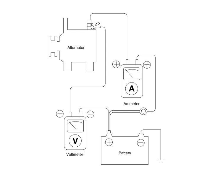
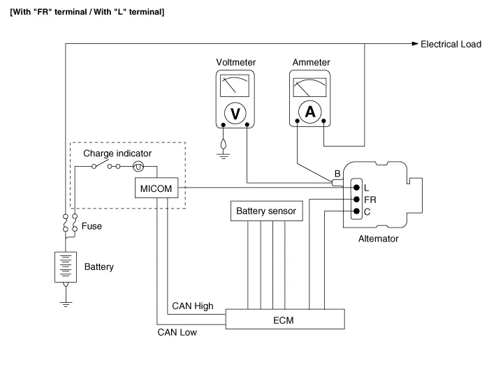
Electrical Specified Value Inspection (Using the Voltmeter and Ammeter)
| 1. | Voltage Drop Test of Alternator Output Wire This
test determines whether or not the wiring between the alternator "B"
terminal and the battery (+) terminal is good by the voltage drop
method. | (1) | Preparation | a. | Turn the ignition switch to "OFF". |
| b. | Disconnect
the output wire from the alternator "B" terminal. Connect the (+) lead
wire of ammeter to the "B" terminal of alternator and the (-) lead wire
of ammeter to the output wire. Connect the (+) lead wire of voltmeter to
the "B" terminal of alternator and the (-) lead wire of voltmeter to
the (+) terminal of battery.
 |
|
| (2) | Test | b. | Turn on the headlamps and blower motor, adjust the engine speed until the ammeter indicates 20A and read the voltmeter. |
|
| (3) | Result | a. | The voltmeter should indicate as specified.
Standard value : 0.2V max |
|
| b. | If
the value of the voltmeter is higher than expected (above 0.2V max.),
poor wiring is suspected. In this case check the wiring from the
alternator "B" terminal to the battery (+) terminal. Check for loose
connections, color change due to an over-heated harness, etc. Correct
them before testing again. |
| c. | Upon completion of the test, set the engine speed at idle. Turn off the headlamps, blower motor and the ignition switch. |
|
|
| 2. | Output Current Test This test determines whether or not the alternator gives an output current equivalent to the normal output. | (1) | Preparation | a. | Prior to the test, check the following items and correct as necessary. Check
the battery installed in the vehicle to ensure that it is in good
condition. Refer to the "Battery" section for checking battery. The battery used to test the output current should be partially discharged. With a fully charged battery, the test may not be conducted correctly due to an insufficient load. Check the tension of the alternator drive belt. Refer to the "Inspect drive belt" section for checking the belt tension. |
| b. | Turn off the ignition switch. |
| c. | Disconnect the battery ground cable. |
| d. | Disconnect the alternator output wire from the alternator "B" terminal. |
| e. | Connect
a DC ammeter (0 to 150A) in series between the "B" terminal and the
disconnected output wire. Be sure to connect the (-) lead wire of the
ammeter to the disconnected output wire. Tighten each connection securely, as heavy current will flow. Do not rely on clips. |
|
| f. | Connect
a voltmeter (0 to 20V) between the "B" terminal and ground. Connect the
(+) lead wire to the alternator "B" terminal and (-) lead wire to a
good ground. |
| g. | Connect the battery ground cable. |
| h. | Leave the engine hood open.
 |
|
| (2) | Test | a. | Check
to see that the voltmeter reads the same as the battery voltage. If the
voltmeter reads 0 V, an open circuit in the wire between alternator "B"
terminal and battery (+) terminal or poor grounding is suspected. |
| b. | Start the engine and turn on the headlamps. |
| c. | Set
the headlamps to high beam and the heater blower switch to HIGH. Then,
quickly increase the engine speed to 2,500 rpm and read the maximum
output current value indicated by the ammeter. | •
| After
the engine start up, the charging current quickly drops. Therefore, the
above operation must be done quickly to read the maximum current value
correctly. |
|
|
|
| (3) | Result | a. | The
ammeter reading must be higher than the limit value. If it is lower
despite the alternator output wire is in good condition, remove the
alternator from the vehicle and test it.
Limit value : 60% of the voltage rate |
• The nominal output current value is shown on the nameplate affixed to the alternator body. |
| •
| The
output current value changes with the electrical load and the
temperature of the alternator itself. Therefore, the nominal output
current may not be obtained. If such is the case, keep the headlamps on
to discharge the battery or use lights of other vehicles to increase the
electrical load. The nominal output current may not be
obtained if the temperature of the alternator itself or ambient
temperature is too high. In such a case, lower the temperature before
testing again. |
|
|
| b. | Upon completion of the output current test, lower the engine speed to idle and turn off the ignition switch. |
| c. | Disconnect the battery negative (-) terminal. |
| d. | Remove the ammeter and voltmeter and the engine tachometer. |
| e. | Connect the alternator output wire to the alternator "B" terminal. |
| f. | Connect the battery negative (-) terminal. |
|
|
| 3. | Regulated Voltage Test The purpose of this test is to check that the electronic voltage regulator controls voltage correctly. | (1) | Preparation | a. | Prior to the test, check the following items and correct if necessary. Check that the battery installed on the vehicle is fully charged. Refer to the "Battery" section for checking the battery. Check the alternator drive belt tension. Refer to the "Inspect drive belt" section for checking the belt tension. |
| b. | Turn ignition switch to "OFF". |
| c. | Disconnect the battery negative (-) terminal. |
| d. | Connect
a digital voltmeter between the "B" terminal of the alternator and
ground. Connect the (+) lead of the voltmeter to the "B" terminal of the
alternator. Connect the (-) lead to good ground or the battery (-)
terminal. |
| e. | Disconnect the alternator output wire from the alternator "B" terminal. |
| f. | Connect
a DC ammeter (0 to 150A) in series between the "B" terminal and the
disconnected output wire. Connect the (-) leadwire of the ammeter to the
disconnected output wire. |
| g. | Connect the battery negative (-) terminal.
|
|
| (2) | Test | a. | Turn on the ignition switch and check to see that the voltmeter indicates the following value.
Voltage : Battery voltage |
If
it reads 0V, there is an open circuit in the wire between the
alternator "B" terminal and the battery and the battery (-) terminal. |
| b. | Start the engine. Keep all lights and accessories off. |
| c. | Run the engine at a speed of about 2,500 rpm and read the voltmeter when the alternator output current drops to 10A or less |
|
| (3) | Result | a. | If the voltmeter reading doesn't agree with the standard value, the voltage regulator or the alternator is faulty.
Regulated Voltage : 11.7 - 15.3V |
|
| b. | If the voltmeter reading doesn't agree with the standard value, the voltage regulator or the alternator is faulty. |
| c. | Disconnect the battery negative (-) terminal. |
| d. | Remove the voltmeter and ammeter. |
| e. | Connect the alternator output wire to the alternator "B" terminal. |
| f. | Connect the battery negative (-) terminal. |
|
|
Electrical Specifications Inspection (Using the Voltmeter and Clamp type Ammeter)
| 1. | Voltage Drop Test of Alternator Output Wire This
test determines whether or not the wiring between the alternator "B"
terminal and the battery (+) terminal is good by the voltage drop
method. | (1) | Preparation | a. | Turn the ignition switch to "OFF". |
| b. | Install the clamp type ammeter between battery positive (+) and alternator "B" terminal. |
| c. | Connect
the (+) lead wire of voltmeter to the "B" terminal of alternator and
the (-) lead wire of voltmeter to the (+) terminal of battery. |
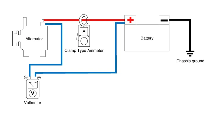 |
| (2) | Test | b. | Turn on the headlamps and blower motor. Then, adjust the engine speed until the ammeter indicates 20A and read the voltmeter. |
|
| (3) | Result | a. | The voltmeter should indicate as specified.
Standard value : 0.2V max |
|
| b. | If
the value of the voltmeter is higher than expected (up to 0.2 V), poor
wiring is suspected. In this case, check the wiring from the alternator
"B" terminal to the battery (+) terminal. Check for loose connections,
color change due to an overheated harness, etc. Correct them before
testing again. |
| c. | Upon completion of the test, set the engine speed at idle.Turn off the headlamps, blower motor and the ignition switch. |
|
|
| 2. | Output Current Test This test determines whether or not the alternator gives an output current equivalent to the normal output. | (1) | Preparation | a. | Prior to the test, check the following items and correct as necessary. Check
the battery installed in the vehicle to ensure that it is good
condition. Refer to the "Battery" section for checking the battery. The battery used to test the output current should be partially discharged. With a fully charged battery, the test may not be conducted correctly due to an insufficient load. Check the tension of the alternator drive belt. Refer to the "Inspect drive belt" section for checking the belt tension. |
| b. | Turn off the ignition switch. |
| c. | Disconnect the battery negative (-) terminal. |
| d. | Install the clamp type ammeter between battery positive (+) and alternator "B" terminal. |
| e. | Connect
a DC ammeter (0 to 150A) in series between the "B" terminal and the
disconnected output wire. Be sure to connect the (-) lead wire of the
ammeter to the disconnected output wire. Tighten each connection securely, as heavy current will flow. Do not rely on clips. |
|
| f. | Connect
a voltmeter (0 to 20V) between the "B" terminal and ground. Connect the
(+) lead wire to the alternator "B" terminal and (-) lead wire to a
good ground. |
| g. | Connect the battery negative (-) terminal. |
| h. | Leave the engine hood open.
|
|
| (2) | Test | a. | Check
to see that the voltmeter reads the same as the battery voltage. If the
voltmeter reads 0 V, an open circuit in the wire between alternator "B"
terminal and battery (+) terminal or poor grounding is suspected. |
| b. | Start the engine and turn on the headlamps. |
| c. | Set
the headlamps to high beam and the heater blower switch to HIGH. Then,
quickly increase the engine speed to 2,500 rpm and read the maximum
output current on the ammeter. | •
| After
the engine start up, the charging current quickly drops. Therefore, the
above operation must be done quickly to read the maximum current value
correctly. |
|
|
|
| (3) | Result | a. | The
ammeter reading must be higher than the limit value. If it is lower
despite the alternator output wire is in good condition, remove the
alternator from the vehicle and test it.
Limit value : 60% of the voltage rate |
• The nominal output current value is shown on the nameplate affixed to the alternator body. |
| •
| The
output current value changes with the electrical load and the
temperature of the alternator itself. Therefore, the nominal output
current may not be obtained. If such is the case, keep the headlamps on
to discharge the battery or use lights of other vehicles to increase the
electrical load. The nominal output current may not be
obtained if the temperature of the alternator itself or ambient
temperature is too high. In such case, lower the temperature before
testing again. |
|
|
| b. | Upon completion of the output current test, lower the engine speed to idle and turn off the ignition switch. |
| c. | Disconnect the battery negative (-) terminal. |
| d. | Remove the ammeter and voltmeter and the engine tachometer. |
| e. | Connect the alternator output wire to the alternator "B" terminal. |
| f. | Connect the battery negative (-) terminal. |
|
|
| 3. | Regulated Voltage Test The purpose of this test is to check that the electronic voltage regulator controls voltage correctly. | (1) | Preparation | a. | Prior to the test, check the following items and correct if necessary. Check that the battery installed on the vehicle is fully charged. Refer to the "Battery" section for checking the battery. Check the alternator drive belt tension. Refer to the "Inspect drive belt" section for checking the belt tension. |
| b. | Turn ignition switch to "OFF". |
| c. | Disconnect the battery negative (-) terminal. |
| d. | Connect
a digital voltmeter between the "B" terminal of the alternator and
ground. Connect the (+) lead of the voltmeter to the "B" terminal of the
alternator. Connect the (-) lead to good ground or the battery (-)
terminal. |
| e. | Disconnect the alternator output wire from the alternator "B" terminal. |
| f. | Connect
a DC ammeter (0 to 150A) in series between the "B" terminal and the
disconnected output wire. Connect the (-) lead wire of the ammeter to
the disconnected output wire. |
| g. | Connect the negative (-) battery terminal.
|
|
| (2) | Test | a. | Turn on the ignition switch and check that the voltmeter indicates the following value.
Voltage : Battery voltage |
If
it reads 0V, there is an open circuit in the wire between the
alternator "B" terminal and the battery and the battery (-) terminal. |
| b. | Start the engine. Keep all lights and accessories turned off. |
| c. | Run the engine at a speed of about 2,500 rpm and read the voltmeter when the alternator output current drops to 10A or less |
|
| (3) | Result | a. | If the voltmeter reading does not agree with the standard value, the voltage regulator or the alternator is faulty.
Regulated Voltage : 11.7 - 15.3V |
|
| b. | If the voltmeter reading does not agree with the standard value, the voltage regulator or the alternator is faulty. |
| c. | Disconnect the negative (-) battery terminal. |
| d. | Remove the voltmeter and ammeter. |
| e. | Connect the alternator output wire to the alternator "B" terminal. |
| f. | Connect the negative (-) battery terminal. |
|
|
Vehicle parasitic current inspection
[Using the Ammeter]
| 1. | Turn all electric devices OFF, and then turn the ignition switch OFF. |
| 2. | Close all doors except the engine hood, and then lock all doors. | (1) | Disconnect the hood switch connector. |
| (3) | Close the doors or remove the door switches. |
|
| 3. | Wait for a few minutes until the vehicle’s electrical systems go to sleep mode. | •
| For
an accurate measurement of a vehicle parasitic current, all electrical
systems should be in sleep mode. (It takes at least one hour or at most
one day.) However, an approximate vehicle parasitic current can be
measured after 10 - 20 minutes. |
|
|
| 4. | Connect
an ammeter in series between the battery (-) terminal and the ground
cable, and then disconnect the clamp from the battery (-) terminal
slowly. | •
| Make
sure that the lead wires of the ammeter are securely connected to
battery (-) terminal and ground to prevent the battery from being reset.
In case the battery is reset, connect the battery cable again, and then
start the engine or turn the ignition switch ON for more than 10
seconds. Repeat the procedure from No. 1. To prevent the battery from being reset during the inspection: |
| 1) | Connect a jump cable between the battery (-) terminal and the ground cable. |
| 2) | Disconnect the ground cable from the battery (-) terminal. |
| 3) | Connect an ammeter between the battery (-) terminal and the ground cable. |
| 4) | After disconnecting the jump cable, read the current value of the ammeter. |
|
 |
| 5. | Read the current value of the ammeter. | •
| If
the parasitic current is over the limit value, search for abnormal
circuit by removing the fuses one by one and checking for parasitic
current. |
| •
|
Reconnect only the fuse suspected of parasitic current and search for
the problematic unit by removing the components connected to the circuit
one by one until the parasitic draw drops below limit value. |
Limit value (after 10 - 20 min.) : Below 50mA |
|
[Using the Clamp type Ammeter]
| 1. | Turn all electric devices OFF, and then turn the ignition switch OFF. |
| 2. | Close all doors except the engine hood, and then lock all doors. | (1) | Disconnect the hood switch connector. |
| (3) | Close the doors or remove the door switches. |
|
| 3. | Wait for a few minutes until the vehicle’s electrical systems go to sleep mode. | •
| For
an accurate measurement of a vehicle parasitic current, all electrical
systems should be in sleep mode. (It takes at least one hour or at most
one day.) However, an approximate vehicle parasitic current can be
measured after 10 - 20 minutes. |
|
|
| 4. | Install the clamp type ammerter on battery negative (-) terminal.
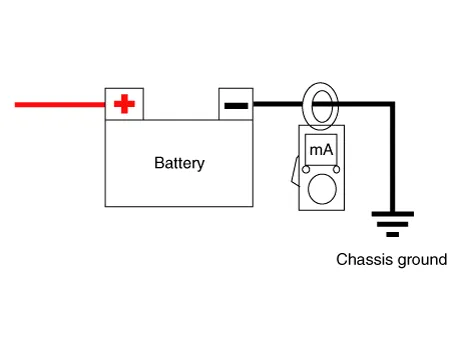 |
| 5. | Read the current value of the ammeter. | •
| If
the parasitic current is over the limit value, search for abnormal
circuit by removing the fuses one by one and checking for parasitic
current. |
| •
| Reconnect
only the fuse suspected of parasitic current and search for the
problematic unit by removing the components connected to the circuit one
by one until the parasitic draw drops below limit value. |
Limit value (after 10 - 20 min.) : Below 50mA |
|
Troubleshooting
Symptom
|
Suspect Area
|
Remedy
|
Charging warning indicator does not
turn ON during ignition switch "ON"
and engine off.
| Fuse blown
| Check fuses
|
Lamp burned out
| Replace light
|
Wiring connection loose
| Tighten loose connection
|
Electronic voltage regulator
| If lamp turns off, replace voltage regulator.
|
Charging warning indicator does not
turn OFF during engine running.
(Battery requires frequent recharging)
| Drive belt loose or worn
| Adjust belt tension or replace belt
|
Battery cable loose, corroded or worn
| Inspect cable connection, repair or replace cable
|
Electronic voltage regulator or alternator
| If light turns off, replace voltage regulator or alternator
|
Wiring
| Repair or replace wiring
|
Overcharge
| Electronic voltage regulator
| If light turns off, replace voltage regulator.
|
Voltage sensing wire
| Repair or replace wiring
|
Discharge
| Drive belt loose or worn
| Adjust belt tension or replace belt
|
Wiring connection loose or short circuit
| Inspect wiring connection, repair or replace wiring
|
Electronic voltage regulator or alternator
| If light turns off, replace voltage regulator or alternator
|
Poor grounding
| Inspect or repair grounding.
|
Worn battery
| Replace battery
|
Specifications
Specification
Ignition System
Spark plug
Item
Specification
Type ELR11ISPC8+ Gap 0.
Specifications
Specification
▷ 13.5V, 120A [ISG only]
Item
Specification
Rated voltage 13.
Other information:
Repair procedures
Removal
1.Disconnect the negative (-) battery terminal.
2.Remove the rear combination lamp (A) after loosening the screws.
3.Remove the rear combination lamp packing (A).
4.Disconnect the rear combination lamp connector (A).
Components and components location
Components
Repair procedures
Inspection
1. Disconnect the negative (-) battery terminal.
2. Remove the map lamp lens (A).
3. Remove the map lamp (B) after loosening the mounting screws.
4.


