Kia Picanto: Body Electrical System / Button Engine Start System
Kia Picanto JA 2017-2025 Service & Repair Manual / Body Electrical System / Button Engine Start System
Components and components location
| Component Location |
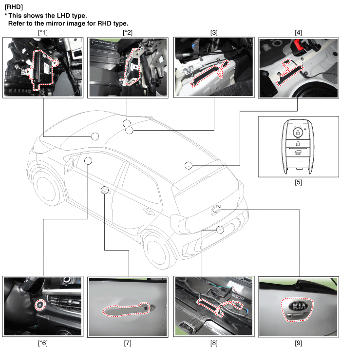
| 1. Body control module (BCM) 2. Smart key unit (SMK) 3. Interior antenna 1 4. Interior antenna 2 5. FOB key | 6. Start Stop Button (SSB) 7. Door handle & door antenna 8. Bumper antenna 9. Tailgate open switch |
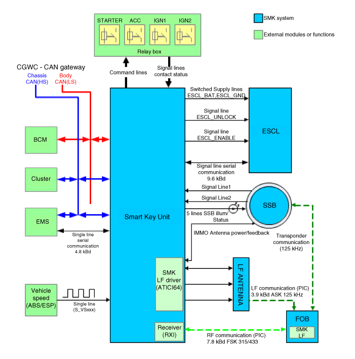
Schematic diagrams
| Circuit Diagram |
Description and operation
| Description |
System Overview
The System offers the following features:
| – | Changing the state of engine ignition and power by using the start button. |
| – | Controlling external relays for ACC / IGN1 / IGN2 terminal switching and STARTER, without use of mechanical ignition switch. |
| – | Indicating the vehicle status on display by using LED or explicit messages. |
| – | Immobilizer function by LF transponder communication between fob and fob holder. |
| – | Redundant architecture for high system dependability . |
| – | Interface with Low Speed CAN vehicle communication network. |
| – | Interface with LIN vehicle communication network depending on platform . |
The
RKE and SMART KEY functions are not considered part of this Button
Engine Start system and are specified in a separate system.
System Main Function
| – | Switching of ACC / IGN1 / IGN2 terminals. |
| – | Control of the STARTER relay BAT line (high side) based on communication with EMS ECU. |
| – | Management of the Immobilizer function. |
| – | Management of BES warning function. |
Button Engine Start System
The
Button Start System allows the driver to operate the vehicle by simply
pressing a button (called as SSB) instead of using a standard mechanical
key.
If the
driver presses the SSB while prerequisites on brakes, fob authentication
and transmission status are satisfied, the BES System will proceed with
the locking/unlocking of the steering column, the control of the
terminal, and the cranking of the engine.
The
driver can release the SSB as soon as this sequence is initiated. After
positive response from immobilizer interrogation, the system will
activate the starter motor and communicate with the EMS to check the
engine running status for starter release.
The
driver will be able to stop the engine by a short push on the SSB if
the vehicle is already in standstill. Emergency engine stop will be
possible by a long press of the SSB or 3 consecutive presses in case the
vehicle is in ENGINE RUNNING.
If
the conditions for engine cranking are not satisfied while a push on
the SSB is detected and a valid fob authenticated, the system will
unlock the steering column and switch the terminals to IGN. Another push
on the SSB will be necessary to start the engine.
In
case of a vehicle equipped with SMART KEY system, fob authentication
will not require any action from the driver. For limp home start or in
case of vehicle without SMART KEY, the driver will have to insert the
fob into the fob holder.
| • | Control Ignition and engine ON/OFF by Sending signal to IPM. |
| • | Display status by LED Lamp ON/OFF. (Amber or Green) |
Indicator ON/OFF Condition At Ignition Key Off Condition
|
No
|
Character lamp
|
Conditions
|
| 1 | Indicator Lamp ON | Door open, Tail lamp ON, ACC, IG ON |
| 2 | Indicator Lamp 30sec ON → Lamp OFF | Door close, Tail lamp OFF, IG OFF |
| 3 | Indicator Lamp OFF | Remote LOCK, Passive LOCK |
| 4 | Rheostat at tail lamp ON (Illumination lamp) | |
Indicator ON/OFF Condition According To Ignition Key's Position
|
No
|
Ignition conditions
|
Start Button LED status
|
| 1 | IG OFF | White color LED ON |
| 2 | IG ACC | Amber color LED ON |
| 3 | IG ON (Engine OFF) | Green color LED ON |
| 4 | Cranking | Maintain LED status before cranking |
| 5 | Engine running | LED OFF |
Operation for each function of button starting
| 1. | Electric power ON / Ignition ON
|
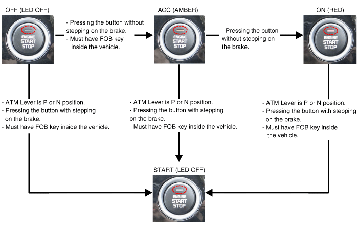
| 2. | Electric power OFF/ Ignition OFF
|
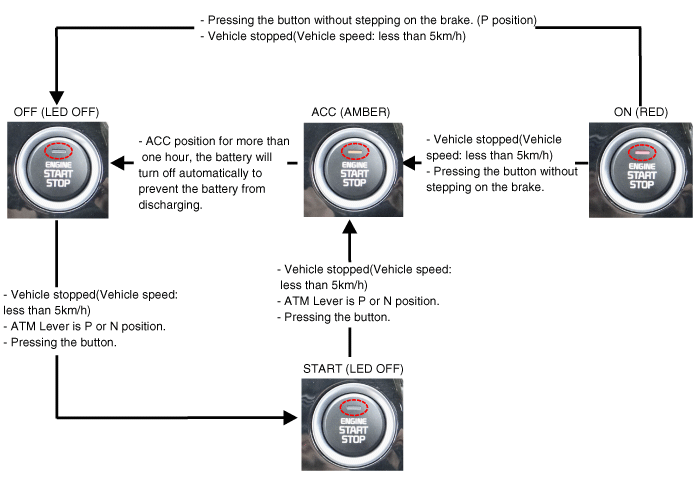
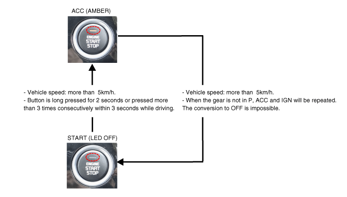
| 3. | How to off the ignition forcibly and to restart during driving
|
| 4. | Function of 0.5 second delay for brake switch input. The
starting is available when the brake pedal is stepped on within 0.5
second after pressing the start button in engine OFF state. |
| 5. | State of start button indicator (LED) ON depending on the electric power state.
|
Limp home mode
| – | In
case of no input signal for the brake (AT specification), the ACC mode
shall move to “START” by pressing SSM for more than 10 seconds. |
| – | In case of problems with communication between EMS and CAN (the EMS state). the “START” state moved to the “ENGINE RUN” based on RPM input. |
| – | In case that one out of two SSM input lines is disconnected, The electric power cycling is available when SSB is pressed twice within 10 seconds (SSB LIMP HOME PRESS) The buzzer rings when the button is pressed in the first time. The electric power cycling is available and buzzer stops when the button is pressed twice within 10 seconds. |
Smart Key Unit
The SMK manages all function related to:
| • | "Start Stop Button (SSB) monitoring", |
| • | "Immobilizer communication" (with Engine Management System unit for immobilizer release), |
| • | "Authentication server" (Validity of Transponder and in case of Smart Key option Passive Fob authentication ), |
| • | "System consistency monitoring", |
| • | "System diagnosis", |
| • | Control of display message / warning buzzer . |
The smart key unit masters the entire button engine start system.
In
case of SMART KEY application, for example "Passive Access”, "Passive
Locking” and "Passive Authorization are integrated for Terminal
switching Operations”.
It
collects information about vehicle status from other modules (vehicle
speed, alarm status, driver door open...), reads the inputs (e.g. SSB,
Capacitive Sensor / Lock Button, PARK position Switch), controls the
outputs (e.g. exterior and interior antennas), and communicates with
others devices via the CAN network as well as a single-line interfaces.
The diagnosis and learning of the components of the BES System are also handled by the SMK.
The
SMK manages the functions related to the "terminal control" by
activating external relays for ACC, IGN1 and IGN2. This unit is also
responsible for the control of the STARTER relay.
The
SMK is also controlling the illumination of the SSB as well as the
"system status indicator", which consists of 2 LEDs of different color.
The illumination of the fob holder is also managed by the SMK.
The
SMK reads the inputs (Engine fob in, vehicle speed, relays contact
status), controls the outputs (Engine relay output drive), and
communicates with others devices via the CAN.
The
internal architecture of the SMK is defined in a way that the control
of the terminal is secured even in case of failure of one of the two
microcontrollers, system inconsistency or interruption of communication
on the CAN network.
In
case of failure of one of the two controllers, the remaining controller
shall disable the starter relay. The IGN1 and IGN2 terminals relays
shall be maintained in the state previously memorized before the failure
and the driver shall be able to switch those IGN terminals off by
pressing the SSB with EMERGENCY_STOP pressing sequence. However, engine
restart will not be allowed. The state of the ACC relay will depend on
the type of failure.
The main functions of the SMK are:
| • | Control of Terminal relays |
| • | Monitoring of the Vehicle speed received from sensor or ABS/ESP ECU. |
| • | Control of SSB LEDs (illumination, clamp state). |
| • | Control of the base station located in SSB through direct serial interface. |
| • | System consistency monitoring to diagnose SMK failure and to switch to relevant limp home mode. |
| • | Providing vehicle speed information |
| • | Start Stop Button (SSB) monitoring |
| • | Starter power control |
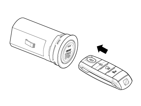
Start/Stop Button (SSB)
A single stage push button is used for the driver to operate the vehicle. Pressing this button allows:
| • | To activate the power modes ‘Off’, ’Accessory’, ‘Ignition’ and 'Start' by switching the corresponding terminals |
| • | To start the engine |
| • | To stop the engine |
The
contact will be insured by a micro-switch and a backlighting is
provided to highlight the marking of the button whenever necessary.
Three (3) LED colors are located in the outside ring of the switch assy. They display the status of the system.
They are OFF(White) / ACC(Amber) / ON(Green).
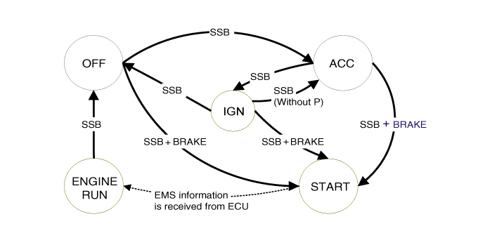
BES(Button Engine Start) System State Chart
System STATES in LEARNING MODE
In learning mode, the BES System can be set in 6 different states, depending on the status of the terminals and Engine status:
|
System State
|
Terminal Status
|
Engine status
|
| 1. OFF - Locked | OFF | Stopped |
| 2. OFF - Unlocked | OFF | Stopped |
| 3. ACC | ACC | Stopped |
| 4. IGN | IGN1, IGN2, ACC | Stopped |
| 5. Start | IGN1, Start | Cranking |
| 6. IGN - Engine | IGN1, IGN2, ACC | Running (means "self-running") |
Referring
to the terminals, the system states described in the table above are
the same as those found in a system based on a mechanical ignition
switch.
One
of the features distinctive from the Mechanical Ignition Switch-based
system is that the BES system allows specific transition from [OFF] to
[START] without going through [ACC] and [IGN] states.
System STATES IN VIRGIN MODE
The
BES System can be set in 5 different states (OFF LOCKED is not
available in virgin mode), depending on the status of the terminals and
Engine status :
|
System State
|
Terminal Status
|
Engine status
|
| 1. OFF - UNLOCKED | OFF | Stopped |
| 2. ACC | ACC | Stopped |
| 3. IGN | IGN1, IGN2, ACC | Stopped |
| 4. Start | IGN1, START with special pattern of activation | Cranking |
| 5. IGN - Engine | IGN1, IGN2, ACC | Running (means "self-running") |
Referring
to the terminals, the system states described in the table above are
the same as those found in a system based on a mechanical ignition
switch.
One
of the features distinctive from the Mechanical Ignition Switch-based
system is that the BES system allows specific transition from [OFF] to
[START] without going through [ACC] and [IGN] states.
 Body Control Module (BCM)
Specifications
Specifications
[BCM Type]
Items
Specifications
Rated voltage DC 12 V Operating voltage DC 9 - 16 V Operating ...
 Start/Stop Button
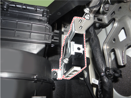
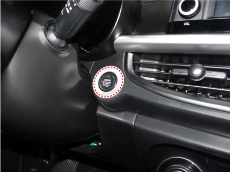
Components and components location
Component
Repair procedures
Removal
1.Disconnect the negative (-) battery terminal.
2.Remove the crash pad lower panel.
(Refer to Bod ...
Other information:
Kia Picanto JA 2017-2025 Owner's Manual: Tilting the sunroof
To open the sunroof, push the sunroof control lever upward until the sunroof moves to the desired position. To close the sunroof, push the sunroof lever forward until the sunroof moves to the desired position. WARNING Make sure heads, other body parts or other objects are safely o ...
Kia Picanto JA 2017-2025 Service & Repair Manual: Timing Chain
Repair procedures Removal 1.Turn the crankshaft pulley and align its groove with the timing mark of the chain cover & oil pump assembly to set the piston of No.1 cylinder to the top dead center on compression stroke. 2.Remove the timing chain cover & oil pump assembly. ...
Copyright © www.kpicanto.com 2017-2025
