Kia Picanto (JA): Brake System / Brake System
Repair procedures
| Operation and Leakage Check |
|
Component
|
Procedure
| |
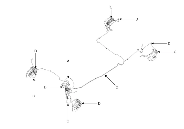
| Brake Booster (A) | Check
brake operation by applying the brakes during a test drive. If the
brakes do not work properly, check the brake booster. Replace the brake
booster as an assembly if it does not work properly or if there are
signs of leakage. | |
| Piston cup and pressure cup inspection (B) | •
Check brake operation by applying the brakes. Look for damage or signs
of fluid leakage. Replace the master cylinder as an assembly if the
pedal does not work properly or if there is damage or signs of fluid
leakage. • Check for a difference in brake pedal stroke between quick and slow brake applications. Replace the master cylinder if there is a difference in pedal stroke. | |
| Brake hoses (C) | Look for damage or signs of fluid leakage. Replace the brake hose with a new one if it is damaged or leaking. | |
| Caliper piston seal and piston boots (D) | Check brake operation by applying the brakes. Look for damage or signs of fluid leakage. If the pedal does not work properly, the brakes drag, or there is damage or signs of fluid leakage, disassemble and inspect the brake caliper. Replace the boots and seals with new ones whenever the brake caliper is disassembled. | |
|

| 1. | Make sure that the brake fluid in the reservoir is at the MAX (upper) level line. |
| 2. | Have someone to slowly pump the brake pedal several times, and then apply pressure. |
| 3. | Loosen the right-rear brake bleed screw (A) to allow air to escape from the system. Then tighten the bleed screw securely. [Front / Rear]
|

| 4. | Repeat the procedure for wheel in the sequence shown below until air bubbles no longer appear in the fluid.
|

| 5. | Refill the master cylinder reservoir to MAX (upper) level line. |
- Brake Booster
- Master Cylinder
- Brake Line
- Brake Pedal
- Front Disc Brake
- Rear Disc Brake
- Rear Drum Brake
- Stop Lamp Switch
Specifications Specifications Item Specification Master cylinder Type Single Cylinder I.
Components and components location Components 1. Brake booster assembly 2. Reservoir 3. Master cylinder
Other information:
Kia Picanto (JA) 2017-2026 Service & Repair Manual: Button Engine Start System
Components and components location Component Location 1. Body control module (BCM) 2. Smart key unit (SMK) 3. Interior antenna 1 4. Interior antenna 2 5. FOB key 6. Start Stop Button (SSB) 7. Door handle & door antenna 8. Bumper antenna 9.
Kia Picanto (JA) 2017-2026 Service & Repair Manual: Headlamp Leveling Actuator
Components and components location Components Repair procedures Removal 1.Disconnect the negative (-) battery terminal. 2.Remove the headlamp assembly. (Refer to Lighting System - "Headlamps") Installation 1.Install the headlamp assembly.
Categories
- Manuals Home
- Kia Picanto Owners Manual
- Kia Picanto Service Manual
- Charging System
- Battery
- Timing Chain
- New on site
- Most important about car
