Kia Picanto: Charging System / Alternator
Specifications
| Specification |
▷ 13.5V, 120A [ISG only]
|
Item
|
Specification
|
| Rated voltage | 13.5V, 120A |
| Speed in use | 1,000 - 18,000 rpm |
| Voltage regulator | IC Regulator built-in type |
| ECM Interface type regulator | LIN communication |
| Regulator Setting Voltage (Internal mode) | 14.5 ± 0.3V |
| Connector | 1 Pin (COM) |
| Pulley Type | OAP |
▷ 13.5V, 90A [NON-ISG]
|
Item
|
Specification
|
| Rated voltage | 13.5V, 90A |
| Speed in use | 1,000 - 18,000 rpm |
| Voltage regulator | IC Regulator built-in type |
| ECM Interface type regulator | LIN communication |
| Regulator Setting Voltage (Internal mode) | 14.5 ± 0.3V |
| Connector | 1 Pin (COM) |
| Pulley Type | OAP |
OAP : Overruning Alternator Pulley |

Components and components location
| Component |
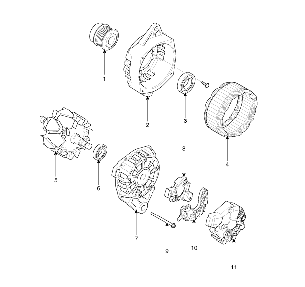
| 1. Pully 2. Front Bracket 3. Front Bearing 4. Stator 5. Rotor 6. Rear Bearing | 7. Rear Bracket 8. Brush Holder Assembly 9. Through Bolt 10. Rectifier Assembly 11. Rear Cover |
Description and operation
| Description |
The Alternator has eight built-in diodes, each rectifying AC current to DC current.
Therefore, DC current appears at alternator "B" terminal.
In addition the charging voltage of this alternator is regulated by the battery voltage detection system.
The main components of the alternator are the rotor, stator, rectifier, capacitor brushes, bearings and V-ribbed belt pulley.
The brush holder contains a built-in electronic voltage regulator.
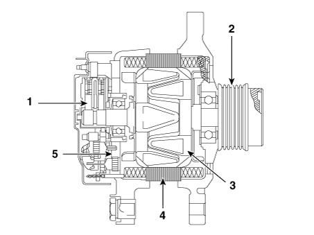
| 1. Brush 2. OAP : Overruning Alternator Pulley 3. Rotor 4. Stator 5. Rectifier |
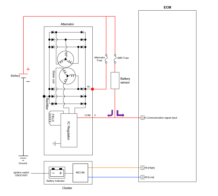
Schematic diagrams
| Circuit Diagram |
|
Repair procedures
| Removal |
| 1. | Turn ignition switch OFF and disconnect the negative (-) battery terminal. |
| 2. | Remove the air cleaner. (Refer to Engine Mechanical System - "Air Cleaner") |
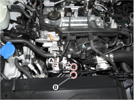
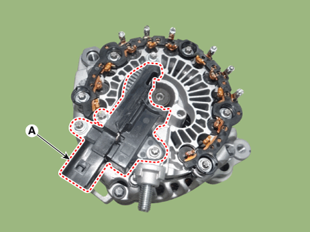
| 3. | Disconnect the alternator connector (A) and alternator "B" cable (B) from the terminal.
|
| 4. | Remove the drive belt. (Refer to Engine Mechanical System - "Drive Belt") |
| 5. | Remove the intake manifold. (Refer to Engine Mechanical System - "Intake Manifold") |
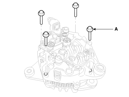
| 6. | Remove the alternator mounting bolts (A).
|
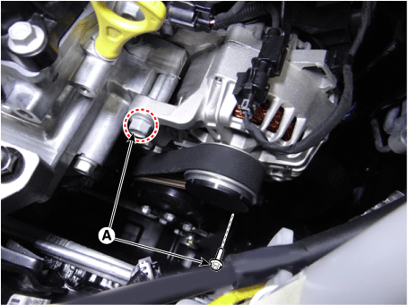
| 7. | Remove the alternator (A).
|

| Installation |
| 1. | Install in the reverse order of removal. |
| Disassembly |
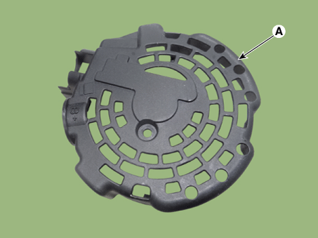
| 1. | Remove the rear cover (A).
|
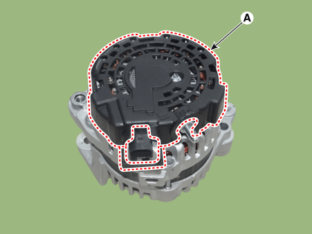
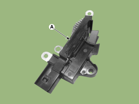
| 2. | Remove the regulator assembly (A) after loosening the mounting bolts.
|

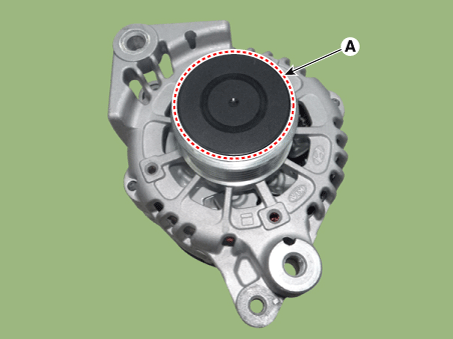
| 3. | Remove the OAP cap (A).
|
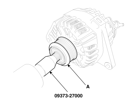
| 4. | Using the SST (09373-27000), remove the OAP pulley (A).
|
| 5. | Remove the rectifier assembly (A) after disconnecting the stator leads.
|
| 6. | Loosen the through bolts (A).
|
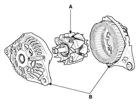
| 7. | Disconnect the rotor (A) and housing (B).
|
| Reassembly |
| 1. | Reassemble in the reverse order of disassembly.
|
| Inspection |
| [Rotor] |
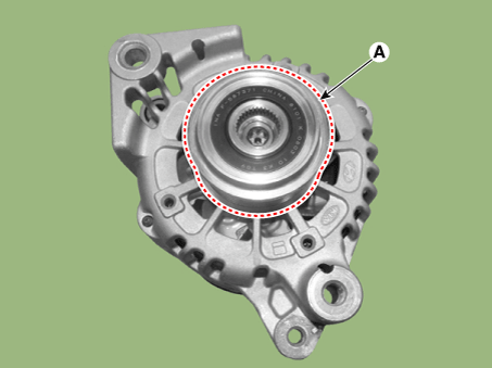
| 1. | Check for continuity between the slip rings (C).
|
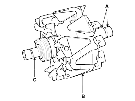
| 2. | Check that there is no continuity between the slip rings and the rotor (B) or rotor shaft (A). |
| 3. | If the rotor fails either continuity checks, replace the alternator. |
| [Stator] |
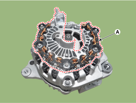
| 1. | Check that there is continuity between each pair of leads (A).
|
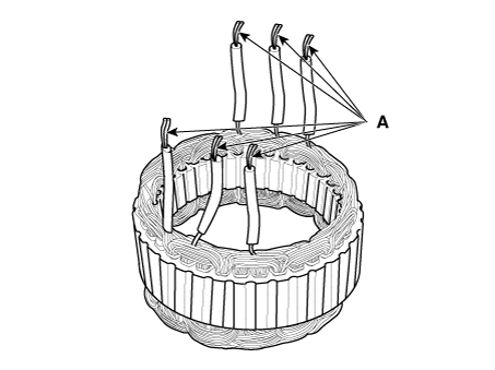
| 2. | Check that there is no continuity between each lead and the coil core. |
| 3. | If the coil fails either continuity checks, replace the alternator. |
 Charging System
Components and components location
Components
① ECM ② Battery
③ Alternator ④ Starter ⑤ Instrument Cluster
⑥ Ignition switch or start/stop button ⑦ Battery sensor
⑧ Hood ...
 DC/DC Converter
Description and operation
Description
Due
to the considerably more frequent occurrence of starting operations,
the electrical load that occurs often leads to voltage dips in the
vehicle ne ...
Other information:
Kia Picanto JA 2017-2025 Service & Repair Manual: Front Seat Frame Assembly
Components and components location Component Location 1. Front seat back frame assembly 2. Front seat cushion frame assembly Repair procedures Replacement • Put on gloves to protect your hands. • ...
Kia Picanto JA 2017-2025 Service & Repair Manual: Engine Mechanical System
Specifications Specifications Description Specification Limit General Type in-line, DOHC Number of cylinders 3 Bore 71.0 mm (2.7952 in.) Stroke 84.0 mm (3.3070 in.) ...
Copyright © www.kpicanto.com 2017-2025
