Kia Picanto (JA): Engine Control System / Accelerator Position Sensor (APS)
Specifications
| Specification |
|
Accelerator
Position |
Output Voltage (V) [Vref = 5V]
| |
|
APS1
|
APS2
| |
| C.T | 0.7 - 0.8 | 0.32 - 0.42 |
| W.O.T | 3.98 - 4.22 | 1.93 - 2.17 |
Description and operation
| Description |
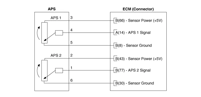
Schematic diagrams
| Circuit Diagram |
| [A/T] |

| [M/T] |
Repair procedures
| Inspection |
| 1. | Connect the KDS on the Data Link Connector (DLC). |
| 2. | Turn the ignition switch ON. |
| 3. | Measure the output voltage of the APS 1 and 2 at C.T and W.O.T.
| |||||||||||

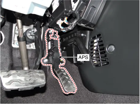
| Removal |
| 1. | Turn the ignition switch OFF and disconnect the battery negative (-) terminal. |
| 2. | Disconnect the accelerator position sensor connector (A). |
| 3. | Remove the installation nuts (B), and then remove the accelerator pedal module.
|

| Installation |
| 1. | Install in the reverse order of removal. |
Specifications Specification Item Specification Rated Voltage (V) 5 Operating Voltage (V) 4.
Specifications Specification Item Specification Coil Resistance (Ω) 1.
Other information:
Kia Picanto (JA) 2017-2025 Service & Repair Manual: Headlamp Leveling Actuator
Components and components location Components Repair procedures Removal 1.Disconnect the negative (-) battery terminal. 2.Remove the headlamp assembly. (Refer to Lighting System - "Headlamps") Installation 1.Install the headlamp assembly.
Kia Picanto (JA) 2017-2025 Service & Repair Manual: Smart Key System
Specifications Specifications Smart Key Unit Items Specification Rated voltage DC 12 V Operating voltage DC 9 - 16 V Operating temperature -31 - 167°F (-35 - 75°C) Load Max. 4mA (When welcome light function "OFF") RF Receiver Items
Categories
- Manuals Home
- Kia Picanto Owners Manual
- Kia Picanto Service Manual
- Air Conditioner Refrigerant/Compressor
- Battery Sensor
- General Information
- New on site
- Most important about car
