Kia Picanto (JA): Driveshaft and axle / Front Axle Assembly
Components and components location
| Components |
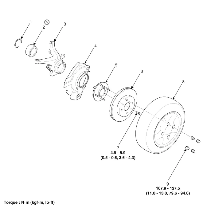
| 1. Snap ring 2. Bearing 3. Axle assembly 4. Brake disc dust cover 5. Wheel hub assembly | 6. Wheel brake disc 7. Brake disc fixing screw 8. Wheel / Tire 9. Wheel nut |
Repair procedures
| Removal |
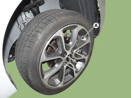
| 1. | Remove the front/rear wheel tire (A).
|

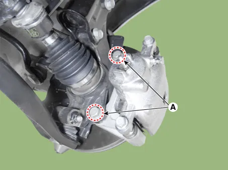
| 2. | Remove the brake caliper mounting bolts (A), and then hold the brake caliper assembly with wire.
|
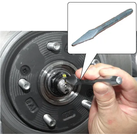
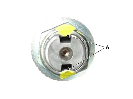
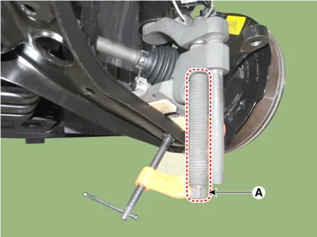
| 3. | By hammering on a chisel, unlock the driveshaft lock hub nut caulking.
|
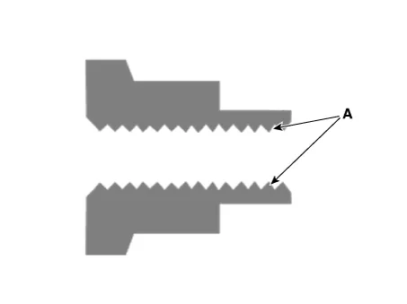
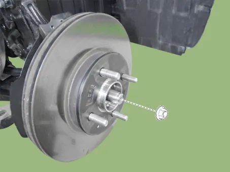
| 4. | Remove the caulking nut from the front axle.
|

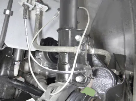
| 5. | Loosen the bolt and then remove the wheel speed sensor.
|

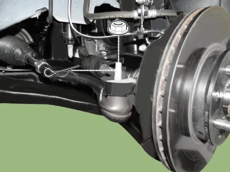
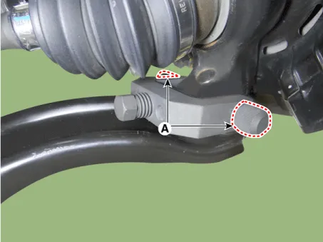
| 6. | Remove the pin and nut from the tie rod end ball joint.
|
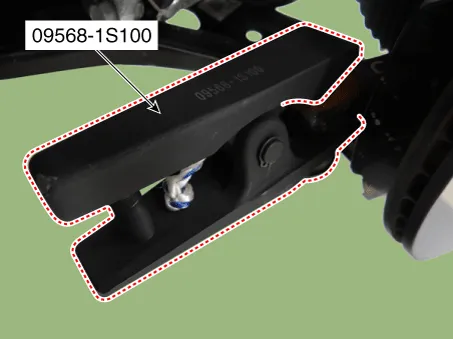
| 7. | Remove the tie rod end ball joint from the knuckle by using the SST (09568-1S100).
|
| 8. | Remove the lower arm bolt and nut (A).
|

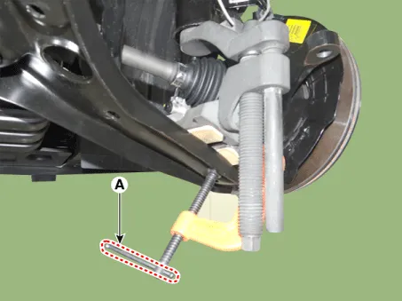
| 9. | Remove the front lower arm from the front knuckle using the SST (0K545-A9100).
|


| 10. | Loosen the screw and then remove the brake disc.
|

| 11. | Loosen the front strut bolts and nuts and then remove the knuckle assembly (A).
|

| Inspection |
| 1. | Check the hub for cracks and the splines for wear. |
| 2. | Check the brake disc for scoring and damage. |
| 3. | Check the knuckle for cracks |
| 4. | Check the bearing for cracks or damage. |
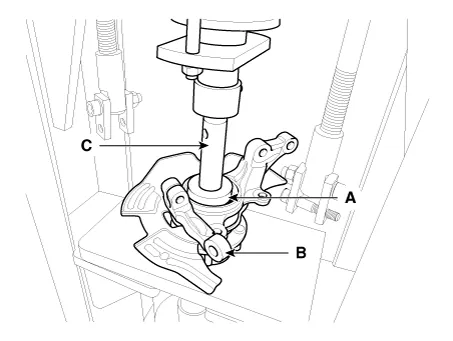
| Disassembly |
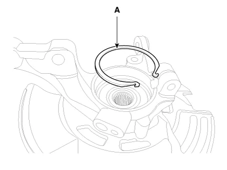
| 1. | Remove the snap ring (A).
|
| 2. | Remove the hub assembly from the knuckle assembly.
|
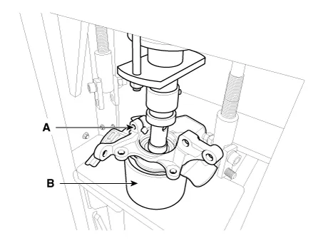
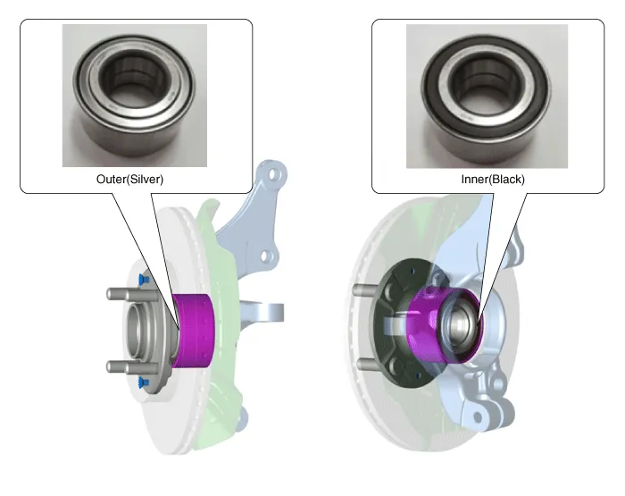
| 3. | Remove the hub bearing inner race from the hub assembly.
|

| 4. | Remove the hub bearing outer race from the knuckle assembly.
|

| 5. | Replace hub bearing with a new one. |
| Reassembly |
| 1. | Install the hub bearing to the knuckle assembly.
|
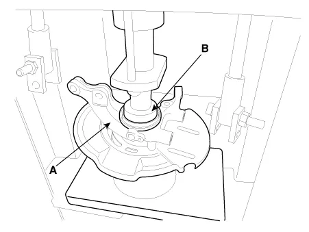

| 2. | Install the hub assembly to the knuckle assembly.
|
| 3. | Install the snap ring (A).
|
Specifications Specification Engine T/M Joint type Max.
Other information:
Kia Picanto (JA) 2017-2026 Service & Repair Manual: Mic
Repair procedures Inspection 1.Disconnect the negative (-) battery terminal. 2.Remove the roof trim assembly. (Refer to Body - "Roof Trim Assembly") 3.Remove the hands free mic (A) after loosening the mounting screws. 4.Check tshe continuity of between terminals.
Kia Picanto (JA) 2017-2026 Service & Repair Manual: Button Engine Start System
Components and components location Component Location 1. Body control module (BCM) 2. Smart key unit (SMK) 3. Interior antenna 1 4. Interior antenna 2 5. FOB key 6. Start Stop Button (SSB) 7. Door handle & door antenna 8. Bumper antenna 9.
Categories
- Manuals Home
- Kia Picanto Owners Manual
- Kia Picanto Service Manual
- Coolant
- Cooling System
- Fuel Delivery System
- New on site
- Most important about car
