Kia Picanto (JA): Cruise Control System / Cruise Control Switch
Kia Picanto (JA) 2017-2025 Service & Repair Manual / Engine Electrical System / Cruise Control System / Cruise Control Switch
Components and components location
| Components |
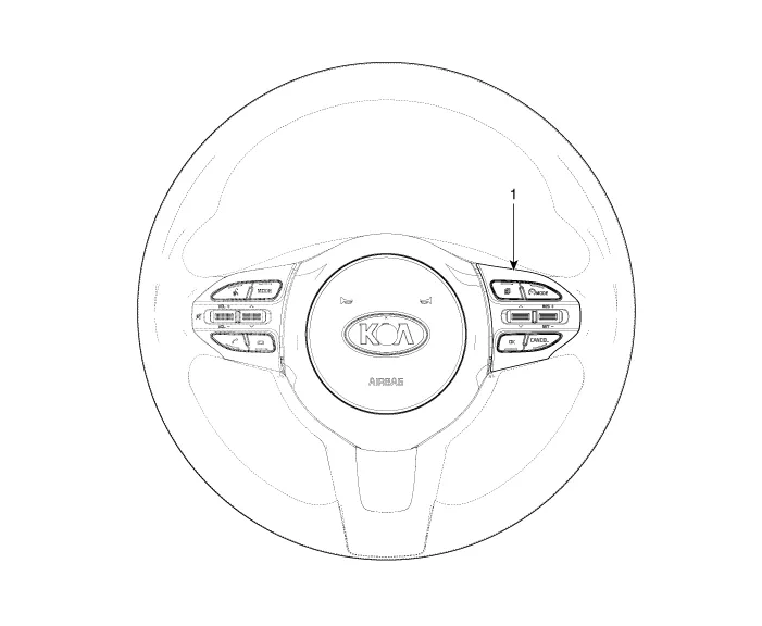
| 1. Right Remote Control Switch (Cruise+Trip Computer) |
Schematic diagrams
| Circuit Diagram |

| [Trip (2 Button) + SEG LCD Cluster] |

| [Trip (2 Button) + ACC + Cruise] |

| [Trip (2 Button) + ACC + Cruise + SLD] |

| [Trip (4 Button) + DOT&TFT LCD Cluster] |

| [Trip (4 Button) + ACC + Cruise] |
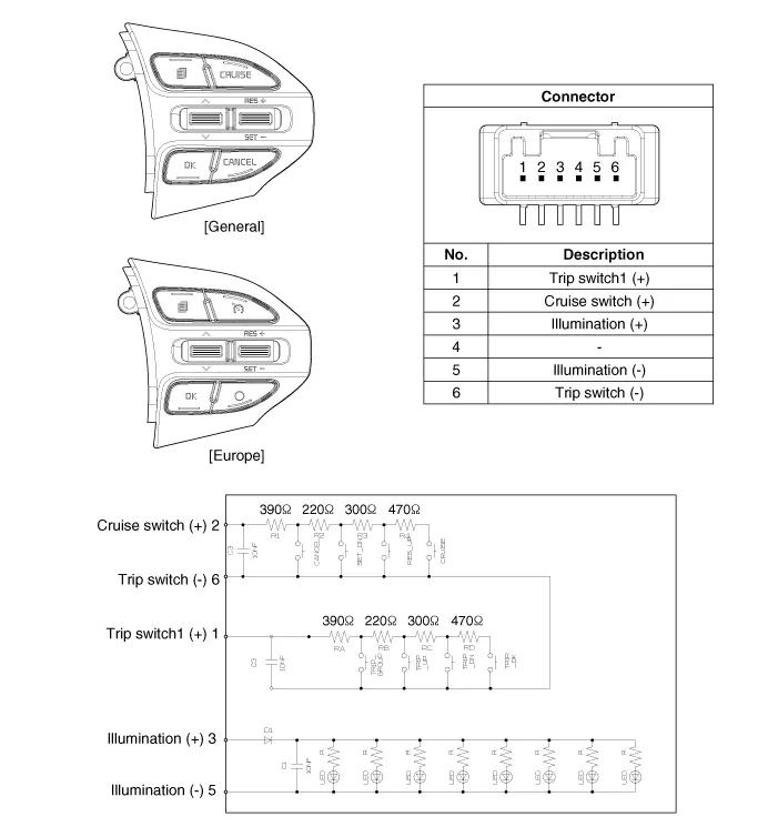
| [Trip (4 Button) + ACC + Cruise + SLD] |

Repair procedures
| Removal |
| 1. | Disconnect the negative (-) battery terminal. |
| 2. | Remove the steering wheel assembly.
(Refer to Steering System - "Steering Wheel")
|
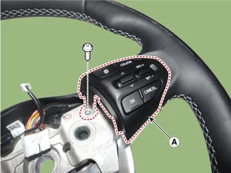
| 3. | Remove the steering wheel remote control (A) after loosening the mounting screws.
|

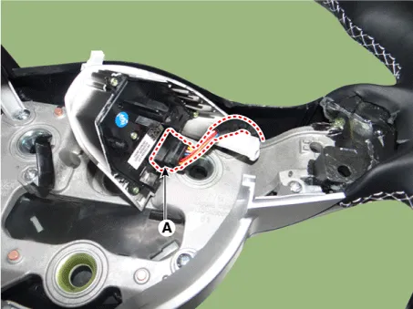
| 4. | Disconnect the steering wheel remote control connector (A).
|
| Installation |
| 1. | Connect the steering wheel remote control connector. |
| 2. | Install the steering wheel remote control. |
| 3. | Install the steering wheel and driver airbag module. |
| 4. | Connect the negative (-) battery terminal. |
| Inspection |
| 1. | Check for resistance between terminals in each switch position.
[RH : Cruise + Trip]
|

Description and operation Description The cruise control system is engaged by the cruise "ON/OFF" main switch located on right of steering wheel column.
Specifications Specifications Purge Control Solenoid Valve (PCSV) ▷ Specification Item Specification Coil Resistance (Ω) 18.
Other information:
Kia Picanto (JA) 2017-2025 Service & Repair Manual: Headlamp Leveling System
C
Kia Picanto (JA) 2017-2025 Service & Repair Manual: Immobilizer Control Unit
Repair procedures Removal 1.Disconnect the negative (-) battery terminal. 2.Remove the main crash pad assembly. (Refer to Body - "Main Crash Pad Assembly") 3.Disconnect the connector of the immobilizer unit and then remove the immobilizer unit (A) after loosening a bolt.
Categories
- Manuals Home
- Kia Picanto Owners Manual
- Kia Picanto Service Manual
- Headlamps
- Battery Sensor
- Fuel Delivery System
- New on site
- Most important about car

Copyright © 2025 www.kpicanto.com - 0.0222