Kia Picanto (JA): Cylinder Block Assembly / Water Jacket Insert
Repair procedures
| Removal and Installation |
| 1. | Remove the cylinder head assembly.
(Refer to Cylinder Head Assembly - "Cylinder Head")
|
| 2. | Remove the water jacket insert inlet (A) and water jacket insert (B).
|
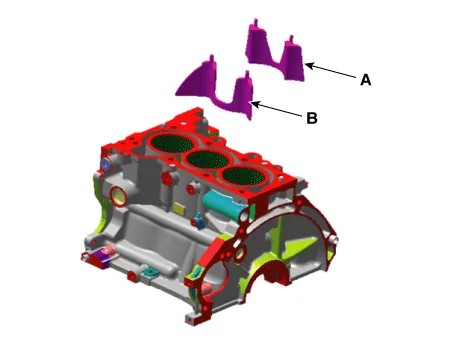

| 3. | Install in the reverse order of removal. |
Repair procedures Removal and Installation 1.Remove the manual transaxle assembly. (Refer to Manual Transaxle System - "Manual Transaxle") 2.
Repair procedures Replacement 1.Remove the transaxle assembly. (Refer to Manual Transaxle System - "Manual Transaxle") 2.Remove the flywheel.
Other information:
Kia Picanto (JA) 2017-2026 Service & Repair Manual: Ignition Switch Assembly
Repair procedures Inspection 1.Disconnect the key warning switch connector (A) and ignition switch connector (B) from the steering column. 2.Check for continuity between the terminals. 3.If continuity is not specified, replace the switch.
Kia Picanto (JA) 2017-2026 Service & Repair Manual: Smart Key System
Specifications Specifications Smart Key Unit Items Specification Rated voltage DC 12 V Operating voltage DC 9 - 16 V Operating temperature -31 - 167°F (-35 - 75°C) Load Max. 4mA (When welcome light function "OFF") RF Receiver Items
Categories
- Manuals Home
- Kia Picanto Owners Manual
- Kia Picanto Service Manual
- Clutch Cable
- Coolant
- Body Electrical System
- New on site
- Most important about car
