Kia Picanto (JA): Steering System / Steering wheel
Components and components location
| Components |

| 1. Bezel 2. Lower cover 3. Steering wheel | 4. Remote switch 5. Wiring 6. Heated steering control unit |
Repair procedures
| Removal |
| 1. | Disconnect the battery negative cable. |
| 2. | Turn the steering wheel so that the front wheels are facing straight ahead. |
| 3. | Remove the driver airbag module.
(Refer to Restraint - "Driver Airbag (DAB) Module and Clock Spring")
|
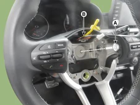
| 4. | Loosen the steering lock bolt (A) and then disconnect the clock spring connector (B).
|

| Disassembly |
| 1. | Loosen the steering wheel lower cover.
|

| 2. | Loosen the steering wheel remote control screw and then disconnect the remote control connector.
|

| 3. | Loosen the bezel screw and then remove the bezel.
|

| 4. | Disconnect the heated control unit connector.
|


| 5. | Loosen the heated control unit screw and then remove the heated control unit.
|

| 6. | Install in the reverse order of removal. |
Specifications Specification Item Specification Type Motor Driven Power Steering Steering gear Type Rack & Pinion Rack stroke 148 ± 1mm (5.
Description and operation Description The heated steering wheel system improves the thermal comfort of the driver by heating the steering wheel when manually selected.
Other information:
Kia Picanto (JA) 2017-2026 Service & Repair Manual: Keyless Entry And Burglar Alarm
Specifications Specification Item Specification Power source 3 V Operating temperature -22 - 167°F (-30 - 75°C) RF Modulation FSK LF Modulation ASK RF frequency 433.92 MHz Button number 3 Function Door lock Door unlock Tailgate unlock Components and components locat
Kia Picanto (JA) 2017-2026 Service & Repair Manual: Rear Glass Defogger Printed Heater
Repair procedures Inspection • Wrap tin foil around the end of the voltmeter test lead to prevent damaging the heater line. Apply pressure on the tin foil with hand and move the tin foil along the grid line to check for open circuits.
Categories
- Manuals Home
- Kia Picanto Owners Manual
- Kia Picanto Service Manual
- Suspension System
- Body Electrical System
- Clutch Cable
- New on site
- Most important about car
