Kia Picanto: Power Windows / Power Window Switch
Kia Picanto JA 2017-2025 Service & Repair Manual / Body Electrical System / Power Windows / Power Window Switch
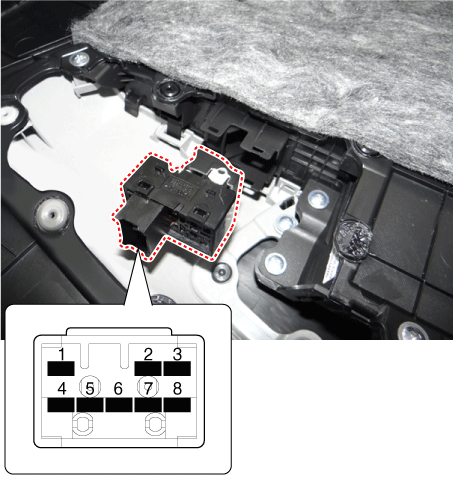
Components and components location
| Components |
| Driver Power Window Switch |
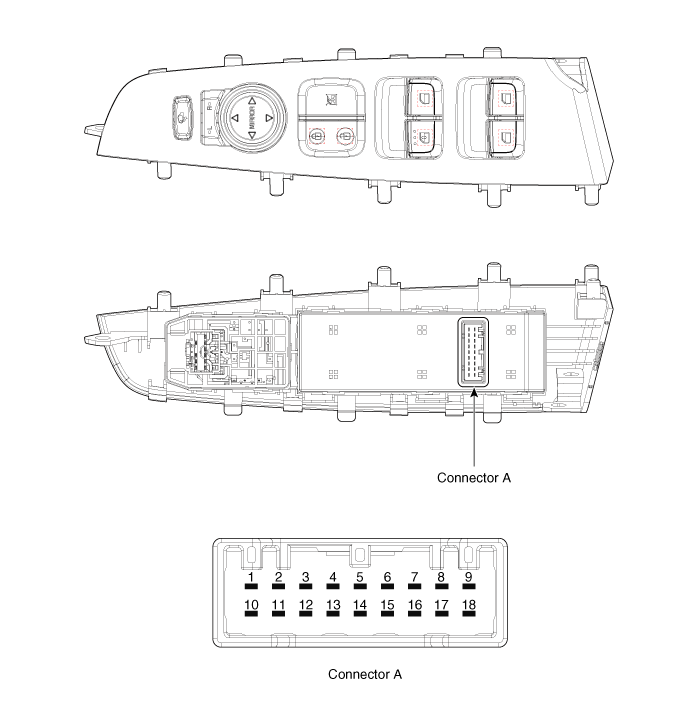
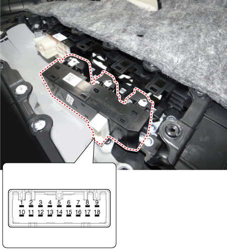
Connector Pin Information
[All Manual / Auto Down Type]
(LHD)
|
No.
|
Description
|
No.
|
Description
|
| 1 | Ground | 10 | Rear left window lock switch |
| 2 | Rear left power window (Down) | 11 | Front left power window (Down) |
| 3 | Rear left power window (Up) | 12 | Front left power window (Up) |
| 4 | Battery (+)_LH | 13 | - |
| 5 | Door unlock switch | 14 | Door lock switch |
| 6 | Battery (+)_Tail lamp | 15 | - |
| 7 | Rear right power window (Down) | 16 | Front right power window (Down) |
| 8 | Rear right power window (Up) | 17 | Front right power window (Up) |
| 9 | Battery (+)_RH | 18 | Rear right window lock switch |
(RHD)
|
No.
|
Description
|
No.
|
Description
|
| 1 | Ground | 10 | - |
| 2 | - | 11 | Front left power window (Down) |
| 3 | - | 12 | Front left power window (Up) |
| 4 | Battery (+)_LH | 13 | - |
| 5 | Door unlock switch | 14 | Door lock switch |
| 6 | Battery (+)_Tail lamp | 15 | - |
| 7 | - | 16 | Front right power window (Down) |
| 8 | - | 17 | Front right power window (Up) |
| 9 | Battery (+)_RH | 18 | - |
[Driver Safety Type]
(LHD)
|
No.
|
Description
|
No.
|
Description
|
| 1 | Ground | 10 | Rear left window lock switch |
| 2 | Rear left power window (Down) | 11 | - |
| 3 | Rear left power window (Up) | 12 | - |
| 4 | Battery (+)_LH | 13 | Driver main power window (Up/Down) |
| 5 | Door unlock switch | 14 | Door lock switch |
| 6 | Battery (+)_Tail lamp | 15 | - |
| 7 | Rear right power window (Down) | 16 | Front right power window (Down) |
| 8 | Rear right power window (Up) | 17 | Front right power window (Up) |
| 9 | Battery (+)_RH | 18 | Rear right window lock switch |
(RHD)
|
No.
|
Description
|
No.
|
Description
|
| 1 | Rear left power window (Down) | 10 | Front left power window (Down) |
| 2 | Rear left power window (Up) | 11 | Ground |
| 3 | - | 12 | Front left power window (Up) |
| 4 | Battery (+)_Tail lamp | 13 | Battery (+)_LH |
| 5 | Rear right power window (Down) | 14 | Battery (+)_RH |
| 6 | Rear right power window (Up) | 15 | Driver main power window (Up/Down) |
| 7 | Door unlock switch | 16 | - |
| 8 | Door lock switch | 17 | - |
| 9 | Rear right window lock switch | 18 | Rear left window lock switch |
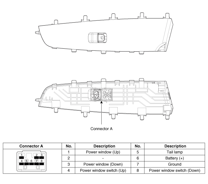
| Assist Power Window Switch |
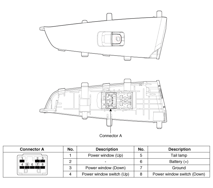
| Rear Power Window Switch |
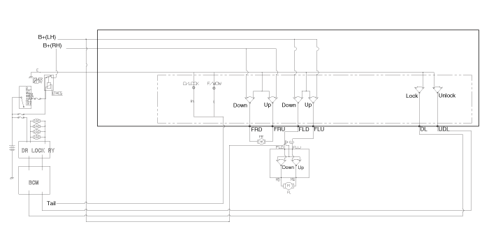
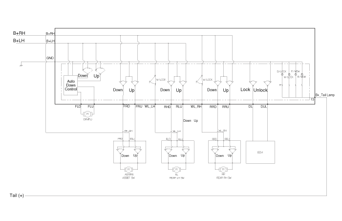
Schematic diagrams
| Circuit Diagram |
| Driver Power Window Switch |
[All Manual Type]
(LHD)
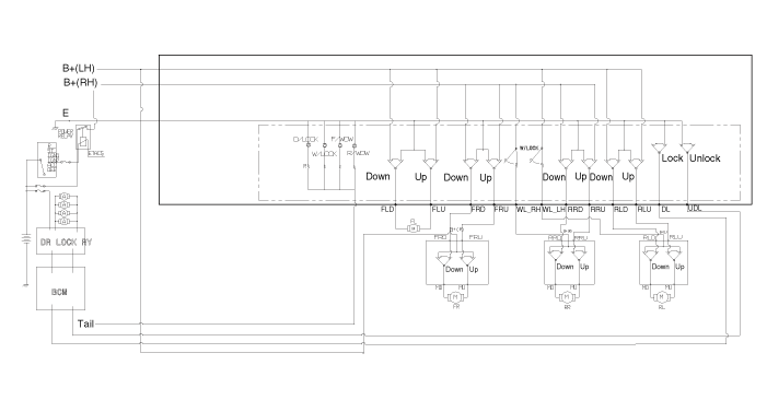
(RHD)
[Auto Down Type]
(LHD)
(RHD)
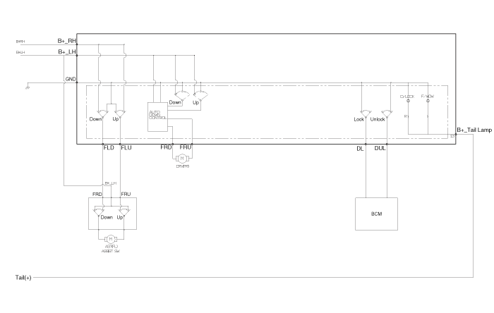
[Driver Safety Type]
(LHD)
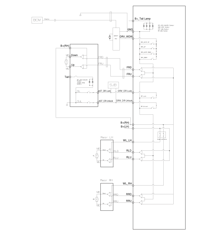
(RHD)
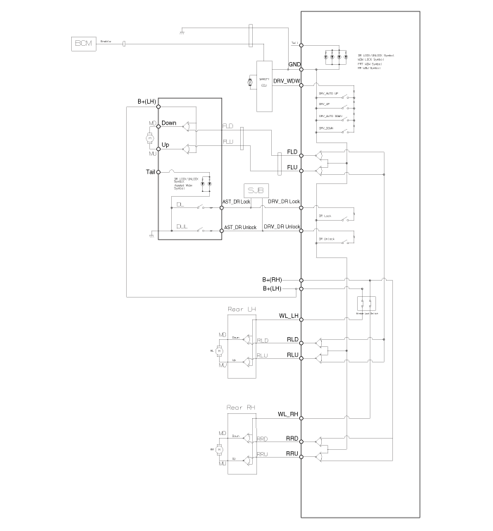
| Assist Power Window Switch |
| Rear Power Window Switch |

Repair procedures
| Removal |
|

Driver Power Window Switch
| 1. | Disconnect the negative (-) battery terminal. |
| 2. | Remove the front left door trim.
(Refer to Body - "Front Door Trim")
|
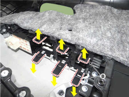
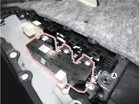
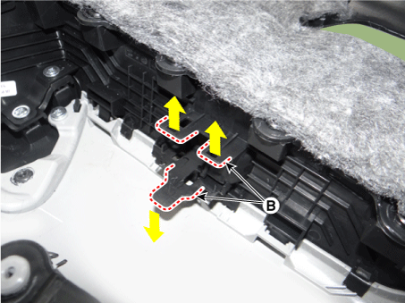
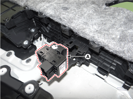
| 3. | Remove the power window switch assembly (A) by pulling out both ends of the switch holders (B).
|
Assist Power Window Switch
| 1. | Disconnect the negative (-) battery terminal. |
| 2. | Remove the front right door trim.
(Refer to Body - "Front Door Trim")
|
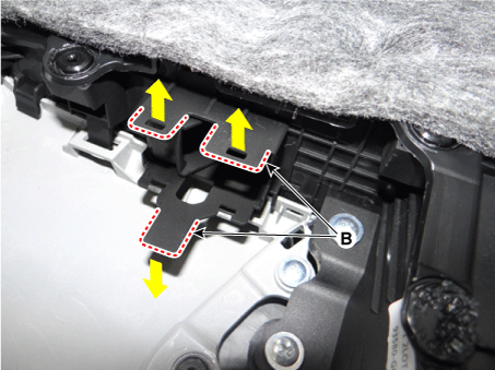
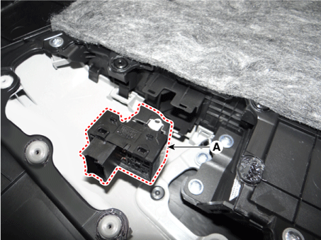
| 3. | Remove the power window switch assembly (A) by pulling out both ends of the switch holders (B).
|
Rear Power Window Switch
| 1. | Disconnect the negative (-) battery terminal. |
| 2. | Remove the rear door trim.
(Refer to Body - "Rear Door Trim")
|
| 3. | Remove the power window switch assembly (A) by pulling out both ends of the switch holders (B).
|
| Installation |
Driver Power Window Switch
| 1. | Install the driver power window switch. |
| 2. | Install the front door trim after connecting the connector. |
| 3. | Connect the negative (-) battery terminal. |
Assist Power Window Switch
| 1. | Install the assist power window switch. |
| 2. | Install the front door trim after connecting the connector. |
| 3. | Connect the negative (-) battery terminal. |
Rear Power Window Switch
| 1. | Install the rear power window switch. |
| 2. | Install the rear door trim after connecting the connector. |
| 3. | Connect the negative (-) battery terminal. |
| Inspection |
Driver Power Window Switch
| 1. | Disconnect the negative (-) battery terminal. |
| 2. | Remove the front left door trim. |
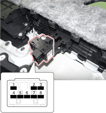
| 3. | Disconnect the power window switch connector from the door trim.
|
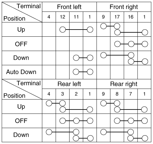
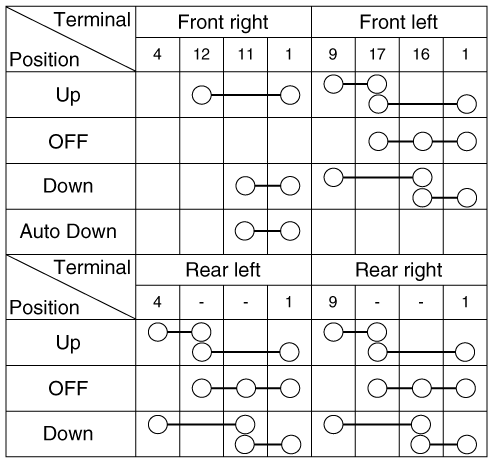
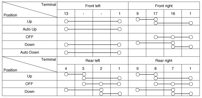
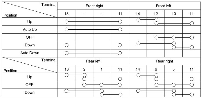
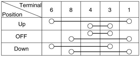
| 4. | Check
for continuity between the terminals in each switch position according
to the table. If the continuity condition is not normal, replace the
switch. [All Manual / Auto Down Type] (LHD)
(RHD)
[Driver Safety Type] (LHD)
(RHD)
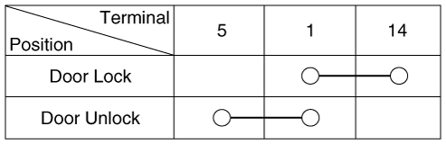
Power Door lock switch
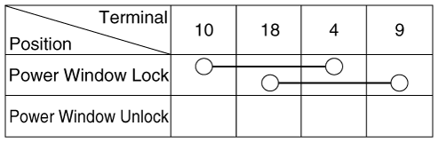
Power Window lock switch
|
Assist / Rear Power Window Switch
| 1. | Disconnect the negative (-) battery terminal. |
| 2. | Remove the front right door trim / rear door trim.
(Refer to Body - "Front Door Trim")
(Refer to Body - "Rear Door Trim")
|
| 3. | Disconnect the power window switch connector from the door trim. [Assist power window switch]
[Rear Power Window Switch]
|
| 4. | Check
for continuity between the terminals in each switch position according
to the table. If the continuity condition is not normal, replace the
switch.
|
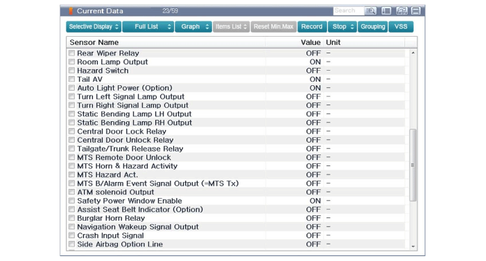
Diagnosis With KDS/GDS
| 1. | The body electrical system can be quickly diagnosed for failed parts by using vehicle diagnostic system (KDS/GDS). The diagnostic system (KDS/GDS) provides the following information.
|
| 2. | Select the 'Car model' and the system to be checked in order to check the vehicle with the tester. |
| 3. | Select the 'Body Control Module (BCM)' to check the Body Control Module (BCM). |
| 4. | Select the "Current Data" menu to search the current state of the input/output data. The input/output data for the sensors corresponding to the door lock switch can be checked.
|
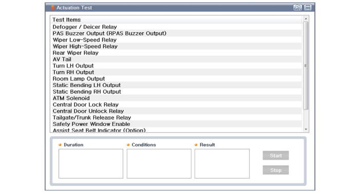
| 5. | If you will check the power door lock operation forcefully, select "Actuation test" of BCM.
|
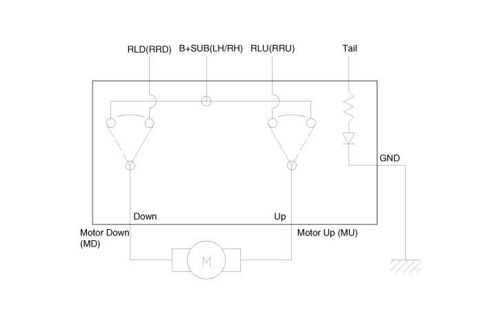
 Power Window Motor
Components and components location
Components
[Standard Window Motor]
[Safety Window Motor]
Repair procedures
Inspection
•
...
 Rear Glass Defogger
Components and components location
Component Location
1. Rear glass defogger relay 2. Rear glass defogger switch (Manual Type) 3. Rear glass defogger switch (FATC Type) 4. Rear glass defogge ...
Other information:
Kia Picanto JA 2017-2025 Service & Repair Manual: Windshield Wiper/Washer
Components and components location Component Location 1. Windshield wiper arm & blade 2. Wiper & washer switch 3. Windshield washer hose & nozzle 4. Wiper motor & linkage assembly 5. Washer motor 6. Washer reservoir tank 7. Wiper/Washer relay 8. Rear washer hose & nolzz ...
Kia Picanto JA 2017-2025 Service & Repair Manual: Heating,Ventilation, Air Conditioning
Specifications Specification Air conditioner Item Specification Compressor Type 5VSe09(Variable Dispacement Swashplate) 5VS09 Oil type & Capacity FD46XG(PAG) 100±10g Pulley type POLY V RIBBED BEIT 6PK Displacement ...
Copyright © www.kpicanto.com 2017-2025
