Kia Picanto (JA): Lubrication System / Oil Pan
Repair procedures
| Removal |
| 1. | Remove the engine room under cover.
(Refer to Engine and Transaxle Assembly - “Engine Room Under Cover”)
|
| 2. | Drain the engine oil.
(Refer to Lubrication System - "Engine Oil")
|
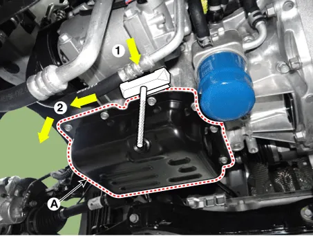
| 3. | Remove the oil pan (A). Insert the blade of SST(09215-3C000) between the ladder frame and the oil pan. Cut out applied sealer and remove the oil pan.
|

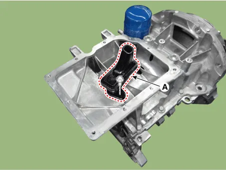
| 4. | Remove the oil screen (A).
|
| Installation |
| 1. | Install the oil screen (A).
|
| 2. | Using a gasket scraper, remove all the old packing material from the gasket surfaces. |
| 3. | Before assembling the oil pan, the liquid sealant should be applied on lower oil pan. Assemble the part within 5 minutes of applying sealant.
|

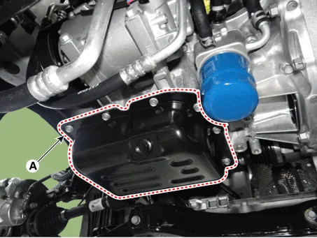
| 4. | Install the oil pan (A). Uniformly tighten the bolts in several passes.
|
| 5. | Install the remaining parts in the reverse order of removal. |
| 6. | Refill with the engine oil.
(Refer to Lubrication System - "Engine Oil")
|
Repair procedures Removal and Installation 1.Remove the engine room under cover. (Refer to Engine and Transaxle Assembly - "Engine Room Under Cover") 2.
Repair procedures Removal and Installation 1.Remove the oil level gauge (A). 2.Remove the timing chain cover & oil pump assembly. (Refer to Timing System - "Timing Chain Cover & Oil Pump Assembly") 3.
Other information:
Kia Picanto (JA) 2017-2026 Service & Repair Manual: Rear Washer Motor
Repair procedures Inspection 1.With the washer motor connected to the reservoir tank, fill the reservoir tank with water. Before filling the reservoir tank with water, check the filter for foreign material or contamination.
Kia Picanto (JA) 2017-2026 Service & Repair Manual: Mode Control Actuator
Components and components location Component Location 1. Mode Control Actuator Description and operation Description The mode control actuator is located at the heater unit. It adjusts position of mode door by operating mode control actuator based on signal of A/C control unit.
Categories
- Manuals Home
- Kia Picanto Owners Manual
- Kia Picanto Service Manual
- Brake System
- Key positions
- Battery
- New on site
- Most important about car
