Kia Picanto (JA): AVN System / Multimedia Jack
Schematic diagrams
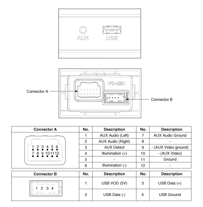
| Circuit Diagram |
Description and operation
| Description |

Repair procedures
| Removal |
Put on gloves to protect your hands. |

|

| 1. | Disconnect the negative (-) battery terminal. |
| 2. | Using a screwdriver or remover, remove the floor console front bezel (A).
|

| 3. | Disconnect the connectors (A) from floor console front bezel.
|
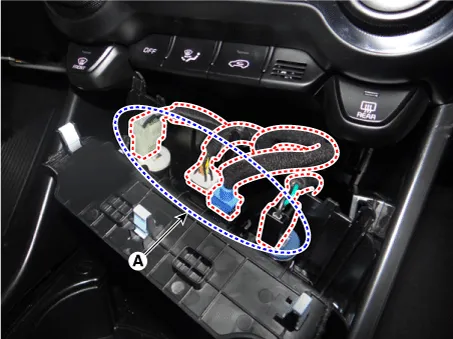
| 4. | Remove the multimedia jack (A) after releasing the fixed hooks.
|


| Installation |
| 1. | Install the multimedia jack. |
| 2. | Connect the connectors from the floor console front bezel. |
| 3. | Install the floor console front bezel. |
| 4. | Connect the negative (-) battery terminal.
|
Components and components location Components 1. Left Remote Control Switch (Audio + Hands free + Voice) 2. Right Remote Control Switch (Cruise+Trip Computer) Schematic diagrams Circuit Diagram [Audio] [Audio + Bluetooth] [Audio + Bluetooth + Voice] [Trip (2 Button) + SEG LCD Cluster] [Trip (2 Button) + ACC] [Trip (2 Button) + ACC + SLD] [Trip (4 Button) + DOT&TFT LCD Cluster] [Trip (4 Button) + ACC] [Trip (4 Button) + ACC + SLD] Repair procedures Removal 1.
Repair procedures Inspection 1.Disconnect the negative (-) battery terminal. 2.Remove the roof trim assembly. (Refer to Body - "Roof Trim Assembly") 3.
Other information:
Kia Picanto (JA) 2017-2026 Service & Repair Manual: AVN Remote Controller
Components and components location Components 1. Left Remote Control Switch (Audio + Hands free + Voice) 2. Right Remote Control Switch (Cruise+Trip Computer) Schematic diagrams Circuit Diagram [Audio] [Audio + Bluetooth] [Audio + Bluetooth + Voice] [Trip (2 Button) + SEG LCD Cluster]
Kia Picanto (JA) 2017-2026 Service & Repair Manual: Immobilizer System
Schematic diagrams Circuit Diaram Description and operation Description The immobilizer system will disable the vehicle unless the proper ignition key is used, in addition to the currently available anti-theft systems such as car alarms, the immobilizer system aims to drastically reduce the rate of auto theft.
Categories
- Manuals Home
- Kia Picanto Owners Manual
- Kia Picanto Service Manual
- Battery
- Suspension System
- Front Disc Brake
- New on site
- Most important about car
