Kia Picanto (JA): Body Electrical System / Multifunction Switch
Specifications
| Specifications |
|
Items
|
Specifications
| |
| Rated voltage | DC 12 V | |
| Operating temperature range | -22 - 176°F (-30 - 80°C) | |
| Rated load | Washer | Washer : 6A (Motor load) |
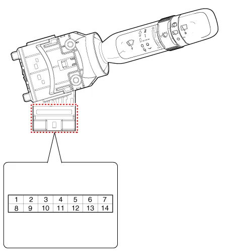
Components and components location
| Component |

| 1 . Steering column shaft 2 . Lighting switch 3 . Wiper/Washer switch | 4 . Screws 5 . Clock spring |
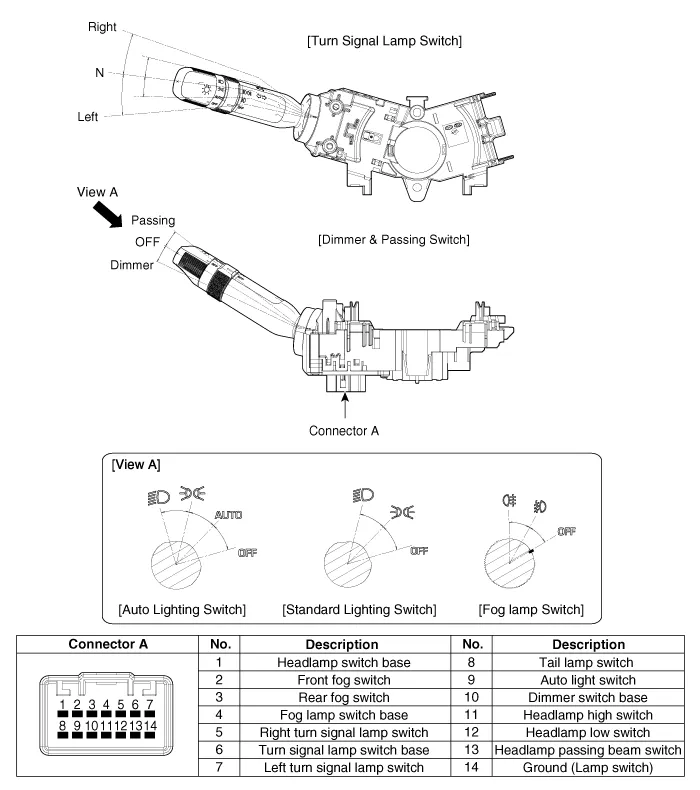
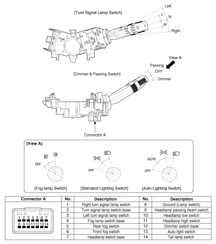
| [Turn Signal Lamp Switch / Dimmer & Passing Switch] |
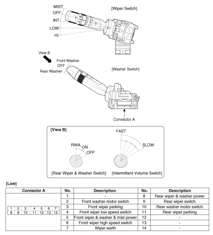
| [Wiper Switch / Washer Switch] |

Repair procedures
| Removal |
| [Turn Signal Lamp Switch / Dimmer & Passing Switch] |
| 1. | Disconnect the negative (-) battery terminal. |
| 2. | Remove the steering column upper and lower shrouds after loosening the screws.
(Refer to Body - "Steering Column Shroud Panal")
|
| 3. | Remove the wiper switch / washer switch.
(Refer to Body Electrical System - "Multifunction Switch")
|
| 4. | Remove the steering wheel.
(Refer to Steering System - "Steering Wheel")
|
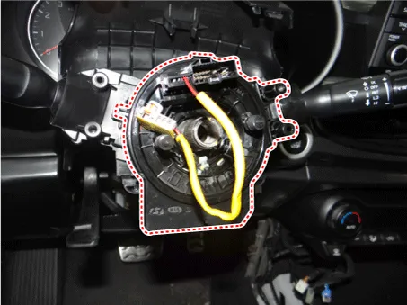
| 5. | Remove the clock spring.
(Refer to Restraint - "Driver Airbag (DAB) Module and Clock Spring")
|
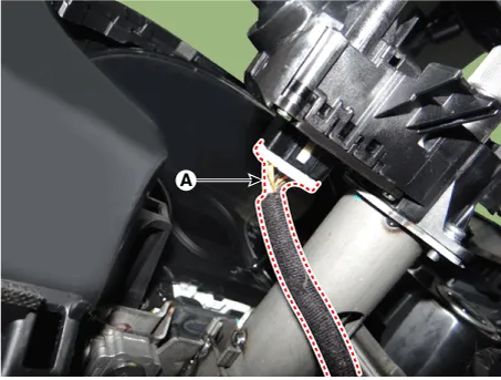
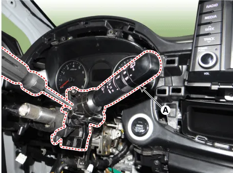
| 6. | Disconnect the turn signal lamp switch / dimmer & passing switch connector (A).
|
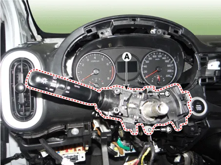
| 7. | Remove the turn signal lamp switch / dimmer & passing switch (A) after loosening the mounting screws.
|
| [Wiper Switch / Washer Switch] |
Work with fully understanding of repair procedure and caution relating to clock spring.
(Refer to Restraint - "Driver Airbag (DAB) Module and Clock Spring")
|

| 1. | Disconnect the negative (-) battery terminal. |
| 2. | Remove the steering column upper and lower shrouds after loosening the screws.
(Refer to Body - "Steering Column Shroud Panal")
|
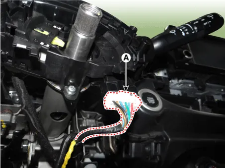
| 3. | Disconnect the wiper switch / washer switch connector (A).
|
| 4. | Remove the wiper switch / washer switch (A) by pushing the lock pin.
|
| Installation |
| [Turn Signal Lamp Switch / Dimmer & Passing Switch] |
| 1. | Install in the reverse order of removal.
|
| 2. | Check
if the steering wheel remote control, airbag system and horn are
normally operating after turning the handle all the way left and right
when installing air bag module is done. |
| [Wiper Switch / Washer Switch] |
| 1. | Install in the reverse order of removal.
|
| 2. | Check
if the steering wheel remote control, airbag system and horn are
normally operating after turning the handle all the way left and right
when installing air bag module is done. |
| Inspection |
| [Turn Signal Lamp Switch / Dimmer & Passing Switch] |
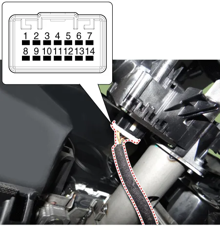
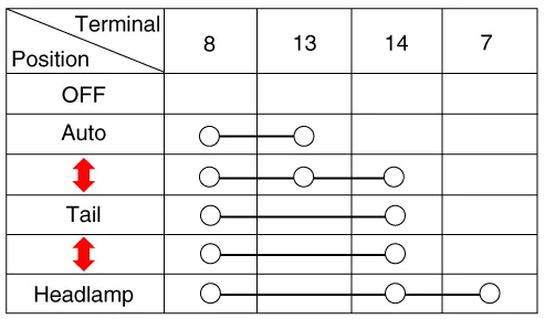
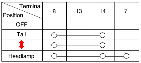
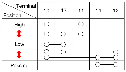
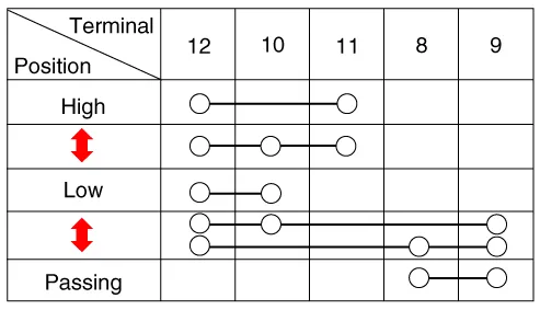
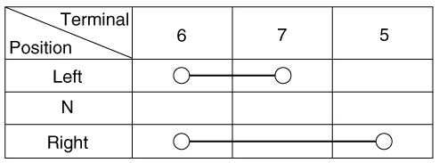
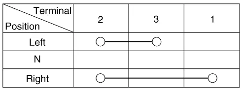
| 1. | Check for continuity between the terminals in each switch position as shown below.
Lighting switch (Auto light) [LHD]
[RHD]
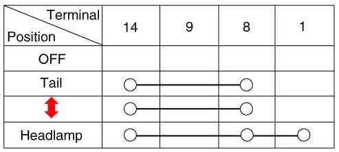
Lighting Switch (Standard) [LHD]
[RHD]
Dimmer And Passing Switch [LHD]
[RHD]
Turn Signal Switch [LHD]
[RHD]
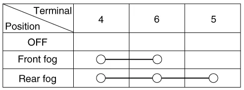
Front/Rear Fog Lamp [LHD]
[RHD]
|


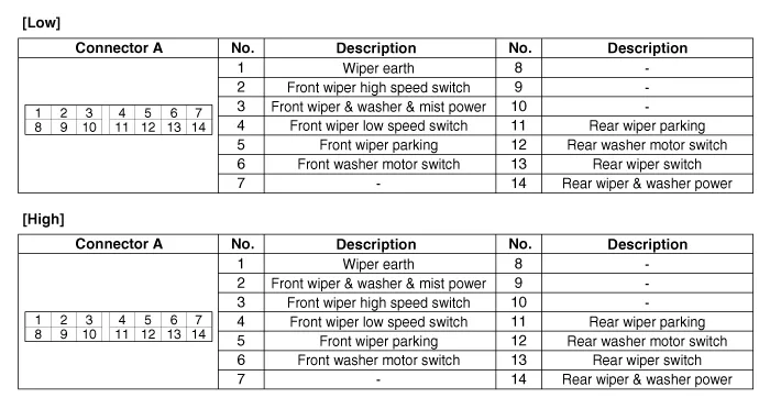
| [Wiper Switch / Washer Switch] |
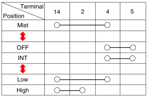
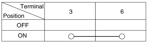
| 1. | Check for continuity between the terminals in each switch position as shown below.
Front Wiper & Washer Switch [LHD]
[RHD]
Front Washer Switch [LHD]
[RHD]
Rear Wiper & Washer Switch [LHD]
[RHD]
|


| Inspection (With KDS/GDS) |
| 1. | In the body electrical system, failure can be quickly diagnosed by using the vehicle diagnostic system (KDS/GDS). The diagnostic system(KDS/GDS) provides the following information.
|
| 2. | Select the 'Car model' and the 'Body Control Module (BCM)' to be checked in order to check the vehicle with the tester. |
| 3. | Select the 'Current Data' menu to search the current state of the input/output data.
|

Repair procedures Removal 1.Disconnect the negative (-) battery terminal. 2.Remove the rear combination lamp (A) after loosening the screws. 3.
Components and components location Component Location 1. Driver power window switch 2. Assist power window switch 3 . Body Comtrol Module (BCM) 4 .
Other information:
Kia Picanto (JA) 2017-2026 Service & Repair Manual: Power Door Lock Module
Components and components location Components 1. Door lock/unlock knob cable 2. Door inside handle cable 3. Door latch assembly Repair procedures Inspection • When removing with a flat-tip screwdriver or remover, wrap protective tape around the tools to prevent damage to
Kia Picanto (JA) 2017-2026 Service & Repair Manual: Sunroof Motor
Repair procedures Inspection 1.Disconnect the negative (-) battery terminal. 2.Remove the roof trim assembly. (Refer to Body - "Roof Trim Assembly") 3.Remove the glass motor (A) after loosening the mounting screws. 4.
Categories
- Manuals Home
- Kia Picanto Owners Manual
- Kia Picanto Service Manual
- Engine Mechanical System
- Cooling System
- Timing Chain
- New on site
- Most important about car
