Kia Picanto (JA): Motor Driven Power Steering / MDPS ECU
Repair procedures
| Replacement |
| 1. | Disconnect the battery negative cable. |
| 2. | Remove the crash pad lower panel. (Refer to Body - "Crash pad lower panel") |
| 3. | Disconnect the MDPS ECU connector.
|
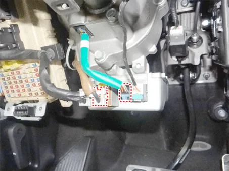
| 4. | Loosen the bolts and then remove the MDPS ECU.
|

| 5. | Installation is the reverse of the removal. |
| 6. | Perform the "Steering Angle Sensor (SAS) Calibration" and "Set the steering feel torque to zero". |
| 7. | Turn off the IGN switch and wait for 10 seconds or more. Then check the operation after starting the engine. |
| Diagnosis with KDS |
|

| 1. | Connect
self-diagnosis connector (16pins) located under the driver side crash
pad to self-diagnosis device, and then turn the self-diagnosis device
after key is ON. |
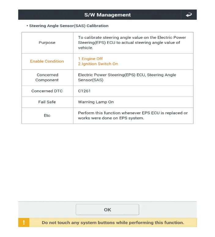
| 2. | Select the "vehicle model" and "Motor Driven Power Steering" on KDS vehicle selection screen. |
| 3. | Select the "Steering Angle Sensor (SAS) Calibration" on KDS screen, then select OK. |
| 4. | Proceed with the test according to the screen instructions.
|


| 5. | Select the "Set the steering feel torque to zero" on KDS screen, then select OK. |
| 6. | Proceed with the test according to the screen instructions.
|


| 7. | Remove the DTC. |
| 8. | Turn off the IG switch and wait for 10 seconds or more before starting the engine. And then make sure that MDPS works properly. |
Repair procedures Replacement 1. Disconnect the battery negative cable. 2. Remove the crash pad lower panel. (Refer to Body - "Crash pad lower panel") 3.
Repair procedures Removal 1. Remove the steering column and shaft assembly. (Refer to Motor Driven Power Steering - "Steering Column and Shaft") 2.
Other information:
Kia Picanto (JA) 2017-2026 Service & Repair Manual: Immobilizer Control Unit
Repair procedures Removal 1.Disconnect the negative (-) battery terminal. 2.Remove the main crash pad assembly. (Refer to Body - "Main Crash Pad Assembly") 3.Disconnect the connector of the immobilizer unit and then remove the immobilizer unit (A) after loosening a bolt.
Kia Picanto (JA) 2017-2026 Service & Repair Manual: Hazard Lamp Switch
Repair procedures Inspection 1.Check for continuity between terminals. If the continuity is not as specified, replace the hazard lamp switch. No. Description No.
Categories
- Manuals Home
- Kia Picanto Owners Manual
- Kia Picanto Service Manual
- Heating,Ventilation, Air Conditioning
- Normal Condition
- Cooling System
- New on site
- Most important about car
