Kia Picanto (JA): Heater / Heater Core
Repair procedures
| Replacement |
| 1. | Disconnect the negative (-) battery terminal. |
| 2. | Remove the heater unit.
(Refer to Heater - "Heater Unit")
|
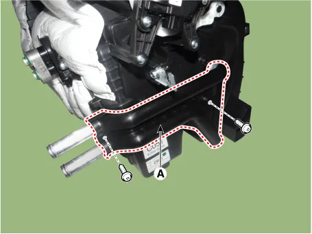
| 3. | Remove the heater core cover (A) after loosening the mounting screws.
|
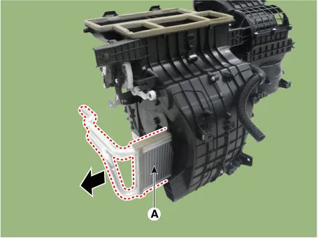
| 4. | Pull out the heater core (A) from the heater unit.
|
| 5. | Install in the reverse order of removal.
|

Components and components location Component Location 1. Mode Control Actuator Description and operation Description The mode control actuator is located at the heater unit.
Repair procedures Replacement 1.Disconnect the negative (-) battery terminal. 2.Remove the heater unit. (Refer to Heater - "Heater Unit") 3.
Other information:
Kia Picanto (JA) 2017-2026 Service & Repair Manual: Back View Camera System
Components and components location Component Location 1. Back view camera 2. AVN head unit 3. steering angle sensor Description and operation Description 1. To display back of the vehicle to assist the driver, it receives vehicle rearside image signal from the rearview camera and displays it on AVN head unit monitor
Kia Picanto (JA) 2017-2026 Service & Repair Manual: Lighting System
Specifications Specification Item Type Bulb Watt (W) Front Headlamp Halogen (Position lamp) Low/High H4 LL 55/60 Turn signal lamp PY21WLL 21 Position lamp W5WLL 5 Halogen (Position lamp + DRL) Low/High HB3 (9005HL+) 60 Turn signal lamp LED LED Po
Categories
- Manuals Home
- Kia Picanto Owners Manual
- Kia Picanto Service Manual
- Cylinder Head
- Timing Chain
- Brake System
- New on site
- Most important about car
