
Kia Picanto (JA): Lighting System / Hazard Lamp Switch
Repair procedures
| Inspection |
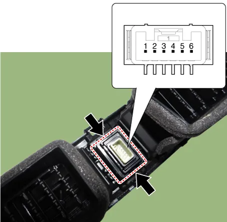
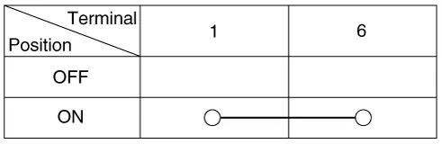
| 1. | Check for continuity between terminals. If the continuity is not as specified, replace the hazard lamp switch.
|
| Removal |
|

| 1. | Disconnect the negative (-) battery terminal |
| 2. | Remove the center fascia panal.
(Refer to Body - "Center Fascia Panel")
|
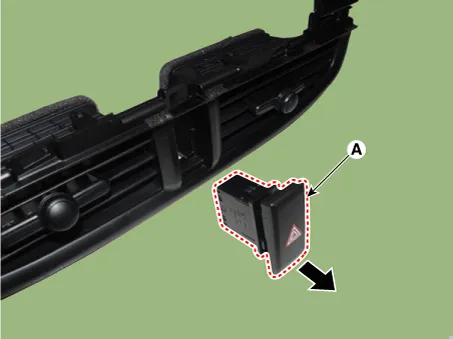
| 3. | Remove the hazard lamp switch (A) by pushing both ends of the switch hooks.
|

| Installation |
| 1. | Install the hazard lamp switch. |
| 2. | Install the center fascia panal. |
| 3. | Connect the negative (-) battery terminal. |
Repair procedures Removal • Put on gloves to prevent hand injuries. • When removing with a flat-tip screwdriver or remover, wrap protective tape around the tools to prevent damage to components.
Repair procedures Removal 1.Disconnect the negative (-) battery terminal. 2.Remove the front bumper assembly. (Refer to Body - "Front Bumper Assembly") 3.
Other information:
Kia Picanto (JA) 2017-2026 Service & Repair Manual: License Lamps
Repair procedures Removal 1. Disconnect the negative (-) battery terminal. 2. Remove the license lamp assembly (A) after pressing the locking pin. 3. Disconnect the license lamp connector (A). 4. Remove the license lamp bulb (B) after removing the license lamp socket (A).
Kia Picanto (JA) 2017-2026 Service & Repair Manual: Sunroof Switch
Components and components location Components Repair procedures Inspection 1. Disconnect the negative (-) battery terminal. 2. Remove the map lamp lens (A). 3. Remove the map lamp (B) after loosening the mounting screws. 4.
Categories
- Manuals Home
- Kia Picanto Owners Manual
- Kia Picanto Service Manual
- Timing Chain
- Thermostat
- Brake System
- New on site
- Most important about car
