Kia Picanto (JA): ABS(Anti-Lock Brake System) / Front Wheel Speed Sensor
Repair procedures
| Removal |
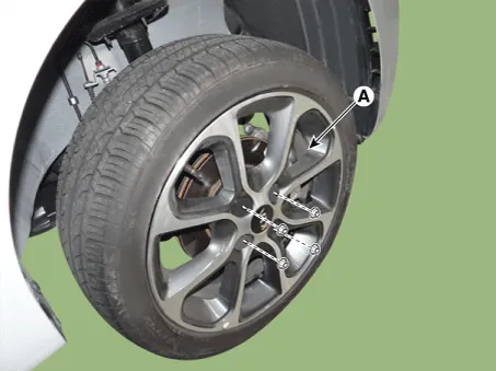
| 1. | Remove the wheel tire (A).
|
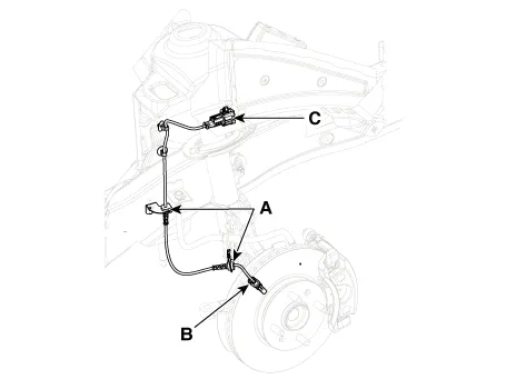
| 2. | Loosen the wheel speed sensor bracket bolts (A),(B) and then disconnect the wheel speed sensor connector (C).
|
| 3. | Install in the reverse order of removal. |
| Inspection |
| 1. | Measure the output voltage between the terminal of the wheel speed sensor and the body ground.
|


| 2. | Compare the change of the output voltage of the wheel speed sensor to the normal change of the output voltage as shown below.
|

Components and components location Components 1. ABS control module connector 2. ABS control module 3. ABS bracket Repair procedures Removal 1.
Repair procedures Removal 1. Remove the wheel tire (A). Tightening torque: 107.9 - 127.5 N·m (11.0 - 13.0 kgf·m, 79.6 - 94.
Other information:
Kia Picanto (JA) 2017-2026 Service & Repair Manual: Power Window Switch
Components and components location Components Driver Power Window Switch Connector Pin Information [All Manual / Auto Down Type] (LHD) No. Description No.
Kia Picanto (JA) 2017-2026 Service & Repair Manual: Smart Key Unit
Components and components location Components Connector Pin Information No. Connector A Connector B Connector C 1 - IGN2 Relay_output Battery (+)_Signal 2 SSB Switch1 signal_input P-CAN (Low) - 3 Driver door o
Categories
- Manuals Home
- Kia Picanto Owners Manual
- Kia Picanto Service Manual
- Front Disc Brake
- Body Electrical System
- Suspension System
- New on site
- Most important about car
