Kia Picanto (JA): Engine And Transaxle Assembly / Engine And Transaxle Assembly
Repair procedures
| Removal |
|

|

| 1. | Remove the air cleaner assembly.
(Refer to Intake and Exhaust System - "Air Cleaner")
|
| 2. | Remove the engine room under cover and side cover.
(Refer to Engine and Transaxle Assembly - Engine Room Under Cover")
|
| 3. | Drain the coolant.
(Refer to Cooling System - "Coolant")
|
| 4. | Recover the refrigerant and then remove the high pressure pipe and low pressure pipe.
(Refer to Heating, Ventilation Air conditioning - "Compressor")
|
| 5. | Remove the battery and battery tray.
(Refer to Engine Electrical System - "Battery")
|
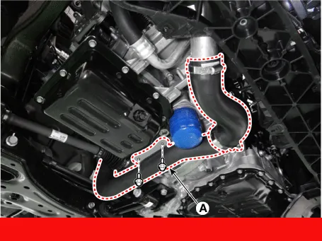
| 6. | Remove the intercooler inlet hoses & pipe (A).
|
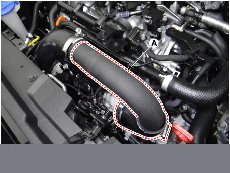
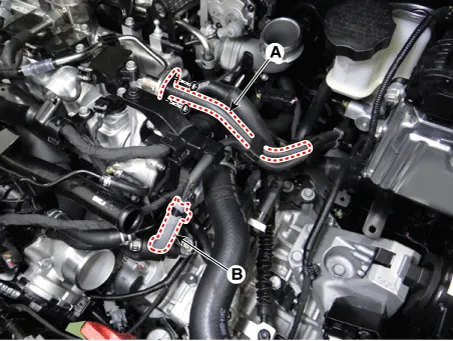
| 7. | Disconnect the intercooler outlet hose & pipe (A)
|
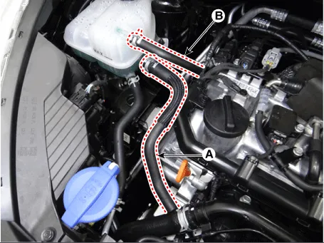
| 8. | Disconnect the water return hose (A) and turbo charger water drain hose (B).
|
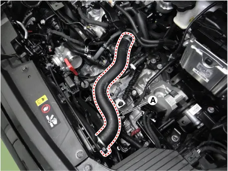
| 9. | Disconnect the radiator upper hose (A).
|
| 10. | Disconnect the radiator lower hose (A).
|

| 11. | Disconnect the fuel hose (A) and purge control solenoid valve (PCSV) hose (B).
|
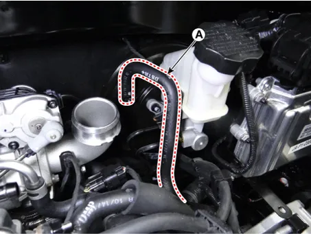
| 12. | Disconnect the brake booster vacuum hose (A).
|
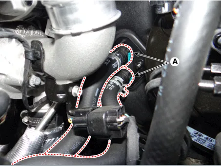
| 13. | Disconnect the recirculation valve (RCV) hose (A) and vacuum hose (B).
|

| 14. | Disconnect the heater hoses (A).
|
| 15. | Disconnect the wiring connectors and harness clamps and remove the connector brackets around the engine and transaxle.
|

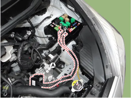
| 16. | Disconnect the fuse box wiring cable (A).
|
| 17. | Remove the transaxle wire harness connectors and control cable from the transaxle.
(Refer to Manual Transaxle System - "Manual transaxle")
|
| 18. | Remove the front muffler.
(Refer to Intake and Exhaust System - "Muffler")
|
| 19. | Remove the roll rod bracket (A).
|
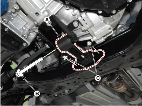
| 20. | Remove the roll rod mounting support bracket (A).
|
| 21. | Remove the sub frame.
(Refer to Suspension system - "Sub frame")
|
| 22. | Support the engine and transaxle assembly with a lift table. |
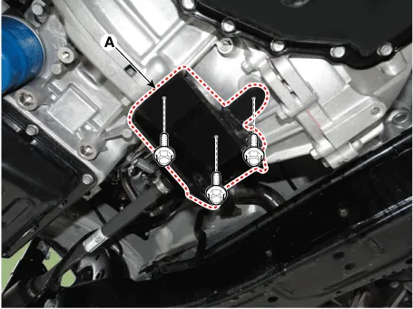
| 23. | Remove the engine mounting bracket (A).
|
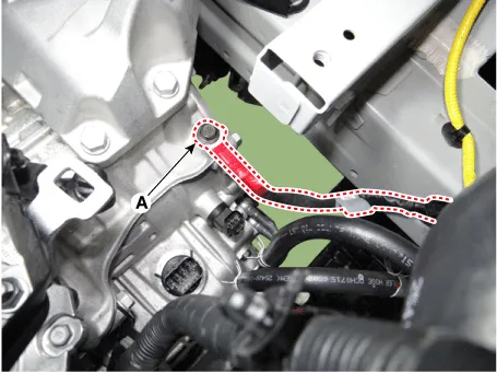
| 24. | Disconnect the transaxle ground cable (A).
|
| 25. | Remove the transaxle side panel packing (A).
|

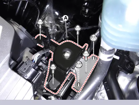
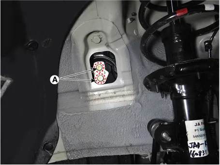
| 26. | Remove the transaxle mounting bolts (A).
|
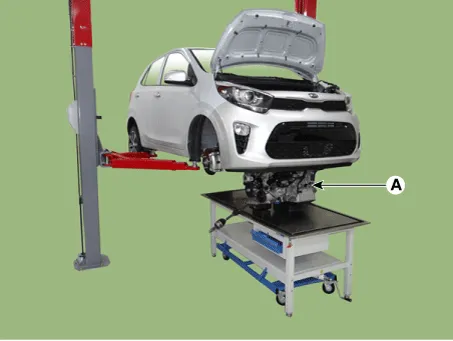
| 27. | Remove the engine and transaxle assembly (A) by lifting vehicle.
|
| Installation |
| • | Refill engine with engine oil. |
| • | Refill transaxle with fluid. |
| • | Refill radiator and reservoir tank with engine coolant. |
| • | Clean battery posts and cable terminals with sandpaper. Then, assemble them and apply grease to prevent corrosion. |
| • | Inspect for fuel leakage. |
| – | After
assembling the fuel line, turn on the ignition switch (do not operate
the starter) so that the fuel pump runs for approximately two seconds
and fuel line pressurizes. |
| – | Repeat this operation two or three times, then check for fuel leakage at any point in the fuel line. |
| • | Switch heater control knob to "HOT" position. |
| • | Bleed air from the cooling system. |
| – | Start engine and let it run until it warms up (until the radiator fan operates 3 or 4 times). |
| – | Turn Off the engine. Check the level in the radiator, and add coolant if needed. This will allow trapped air to be released from the cooling system. |
| – | Put radiator cap on tightly, then run the engine again and check for leaks. |
Components and components location Components 1. Engine mounting bracket 2. Roll rod bracket 3. Transaxle mounting bracket Repair procedures Removal and Installation Engine Mounting Bracket 1.
Other information:
Kia Picanto (JA) 2017-2026 Service & Repair Manual: Mic
Repair procedures Inspection 1.Disconnect the negative (-) battery terminal. 2.Remove the roof trim assembly. (Refer to Body - "Roof Trim Assembly") 3.Remove the hands free mic (A) after loosening the mounting screws. 4.Check tshe continuity of between terminals.
Kia Picanto (JA) 2017-2026 Service & Repair Manual: Temperature Control Actuator
Components and components location Component Location 1. Temerature Control Actuator Description and operation Description 1. Heater unit includes mode control actuator and temperature control actuator. 2. Temperature control actuator is located at the heater unit.
Categories
- Manuals Home
- Kia Picanto Owners Manual
- Kia Picanto Service Manual
- Heating,Ventilation, Air Conditioning
- Fuel Delivery System
- Front Disc Brake
- New on site
- Most important about car
