Kia Picanto (JA): Drive Belt System / Drive Belt
Repair procedures
| Removal and Installation |
| 1. | Remove the engine room under cover.
(Refer to Engine and Transaxle Assembly - "Engine Room Under Cover")
|
| 2. | Using the wrench, turning the auto tensioner pulley (A) counterclockwise and then insert a stopper pin (B) into the hole.
|
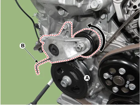
| 3. | Remove the drive belt (A).
|

| 4. | Install in the reverse order of removal. |
| Inspection |
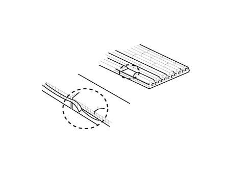
| 1. | Visually check the belt for excessive wear, frayed cords etc. If any defect has been found, replace the drive belt.
|

Repair procedures Removal and Installation 1.Remove the engine room under cover. (Refer to Engine and Transaxle Assembly - "Engine Room Under Cover") 2.
Other information:
Kia Picanto (JA) 2017-2026 Service & Repair Manual: Lighting System
Specifications Specification Item Type Bulb Watt (W) Front Headlamp Halogen (Position lamp) Low/High H4 LL 55/60 Turn signal lamp PY21WLL 21 Position lamp W5WLL 5 Halogen (Position lamp + DRL) Low/High HB3 (9005HL+) 60 Turn signal lamp LED LED Po
Kia Picanto (JA) 2017-2026 Service & Repair Manual: Smart Key Unit
Components and components location Components Connector Pin Information No. Connector A Connector B Connector C 1 - IGN2 Relay_output Battery (+)_Signal 2 SSB Switch1 signal_input P-CAN (Low) - 3 Driver door o
Categories
- Manuals Home
- Kia Picanto Owners Manual
- Kia Picanto Service Manual
- Body Electrical System
- Automatic Transaxle Fluid
- Battery
- New on site
- Most important about car
