Kia Picanto (JA): Cylinder Block Assembly / Cylinder Block
Repair procedures
| Disassembly |
|

|

| 1. | Remove the engine and transaxle assembly.
(Refer to Engine and Transaxle Assembly - "Engine And Transaxle Assembly")
|
| 2. | Remove the transaxle assembly from the engine assembly.
(Refer to Manual Transaxle System - "Manual Transaxle")
|
| 3. | Remove the flywheel.
(Refer to Cylinder Block Assembly - "Flywheel")
|
| 4. | Remove the rear oil seal.
(Refer to Cylinder Block Assembly - "Rear Oil Seal")
|
| 5. | Install the engine assembly to engine stand for disassembly. |
| 6. | Remove the cylinder head cover.
(Refer to Cylinder Head Assembly - “Cylinder Head Cover”)
|
| 7. | Remove the thermostat housing.
(Refer to Cooling System - “Thermostat”)
|
| 8. | Remove the timing chain.
(Refer to Timing System - “Timing Chain”)
|
| 9. | Remove the intake manifold.
(Refer to Intake and Exhaust System - "Intake Manifold")
|
| 10. | Remove the turbo manifold module.
(Refer to Intake and Exhaust System - "Turbo Manifold Module")
|
| 11. | Remove the cylinder head.
(Refer to Cylinder Head Assembly - “Cylinder Head”)
|
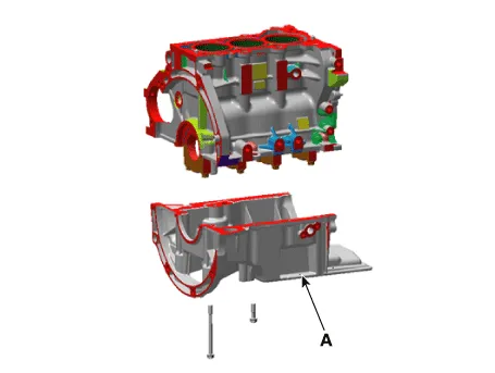
| 12. | Remove the oil pan and the oil screen.
(Refer to Lubrication System - “Oil pan”)
|
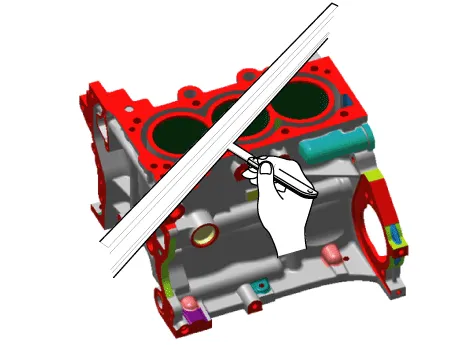
| 13. | Remove the ladder frame (A). Insert
the blade of SST (09215-3C000) between the cylinder block and the
ladder frame and cut out applied sealer. Then, remove the ladder frame.
|

| 14. | Check the connecting rod side clearance.
(Refer to Cylinder Block Assembly - "Piston And Connecting Rod")
|
| 15. | Check the connecting rod cap oil clearance.
(Refer to Cylinder Block Assembly - "Piston And Connecting Rod")
|
| 16. | Remove the piston and connecting rod assemblies.
(Refer to Cylinder Block Assembly - "Piston and Connecting Rod")
|
| 17. | Check the main bearing oil clearance.
(Refer to Cylinder Block Assembly - "Crankshaft")
|
| 18. | Check the crankshaft end play.
(Refer to Cylinder Block Assembly - "Crankshaft")
|
| 19. | Remove the crankshaft.
(Refer to Cylinder Block Assembly - "Crankshaft")
|
| 20. | Remove the water jacket insert.
(Refer to Cylinder block - "Water Jacket Insert")
|
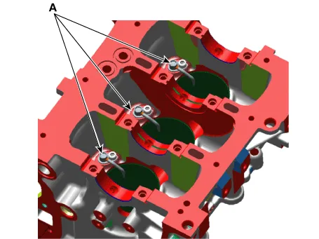
| 21. | Remove the oil jet (A).
|
| Inspection |
| 1. | Remove the gasket material. Using a gasket scraper, remove all the gasket material from the top surface of the cylinder block. |
| 2. | Clean the cylinder block. Using a soft brush and solvent, thoroughly clean the cylinder block. |
| 3. | Inspect the top surface of the cylinder block for flatness. Using a precision straight edge and feeler gauge, measure the surface contacting the cylinder head gasket for warpage.
|
| 4. | Inspect the cylinder bore. Visually check the cylinder for vertical scratches. If deep scratches are present, replace the cylinder block. |
| 5. | Inspect the cylinder bore diameter. Using a cylinder bore gauge, measure the cylinder bore diameter at position in the thrust and axial direction.
|

| Reassembly |
| 1. | Install the oil jet (A).
|
| 2. | Install the water jacket insert.
(Refer to Cylinder block - "Water Jacket Insert")
|
| 3. | Install the crankshaft.
(Refer to Cylinder Block Assembly - "Crankshaft")
|
| 4. | Check the crankshaft end play.
(Refer to Cylinder Block Assembly - "Crankshaft")
|
| 5. | Check the main bearing oil clearance.
(Refer to Cylinder Block Assembly - "Crankshaft")
|
| 6. | Install the piston and connecting rod assemblies.
(Refer to Cylinder Block Assembly - "Piston and Connecting Rod")
|
| 7. | Check the connecting rod cap oil clearance.
(Refer to Cylinder Block Assembly - "Piston And Connecting Rod")
|
| 8. | Check the connecting rod side clearance.
(Refer to Cylinder Block Assembly - "Piston And Connecting Rod")
|
| 9. | Install the ladder frame.
|


| 10. | Assemble the remaining parts in the reverse order of disassembly.
|
Repair procedures Disassembly • Use fender covers to avoid damaging painted surfaces.• To avoid damaging the cylinder head, wait until the engine coolant temperature drops below normal temperature (20°C [68°F]) before removing it.
Components and components location Components 1. Cylinder head gasket 2. Cylinder head 3. Intake oil control valve (OCV) 4. Exhaust oil control valve (OCV) 5.
Other information:
Kia Picanto (JA) 2017-2026 Service & Repair Manual: Front Washer Motor
Repair procedures Inspection Front Washer Motor 1.With the washer motor connected to the reservoir tank, fill the reservoir tank with water. • Before filling the reservoir tank with water, check the filter for foreign material or contamination.
Kia Picanto (JA) 2017-2026 Service & Repair Manual: Intake Actuator
Components and components location Component Location 1. Intake Actuator Description and operation Description 1. The intake actuator is located at the blower unit. 2. It regulates the intake door by signal from control unit.
Categories
- Manuals Home
- Kia Picanto Owners Manual
- Kia Picanto Service Manual
- Suspension System
- Charging System
- Engine Control / Fuel System
- New on site
- Most important about car
