Kia Picanto (JA): Drive Belt System / Crankshaft Damper Pulley
Repair procedures
| Removal and Installation |
| 1. | Remove the engine room under cover and RH side cover.
(Refer to Engine and Transaxle Assembly - "Engine Room Under Cover")
|
| 2. | Remove the drive belt.
(Refer to Drive Belt System - "Drive Belt")
|
| 3. | Remove the RH side front wheel.
(Refer to Suspension System - "Wheel")
|
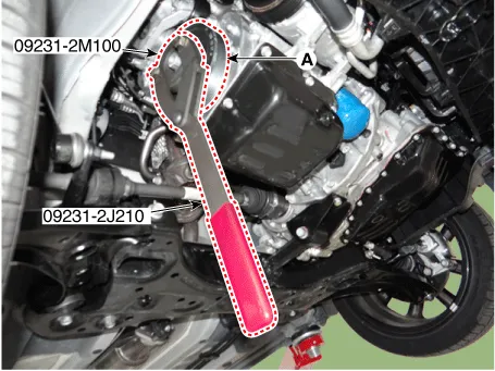
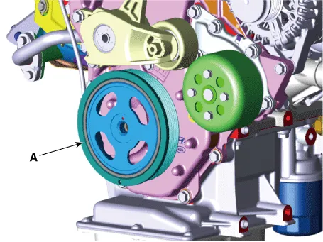
| 4. | Remove the crankshaft damper pulley.
|
| 5. | Install in the reverse order of removal. |
| Inspection |
Repair procedures Removal and Installation 1.Remove the engine room under cover. (Refer to Engine and Transaxle Assembly - "Engine Room Under Cover") 2.
Other information:
Kia Picanto (JA) 2017-2026 Service & Repair Manual: Headlamp Leveling Switch
Schematic diagrams Circuit Diagram Repair procedures Removal 1.Disconnect the negative (-) battery terminal. 2.Remove the crash pad lower panel. (Refer to Body - "Crash Pad Lower Panel") 3.Remove the crash pad side switch (A) after loosening the mounting screws.
Kia Picanto (JA) 2017-2026 Service & Repair Manual: Power Door Lock Switch
Repair procedures Inspection 1.Check for continuity between the terminals. If there is an abnormality, replace the switch. Removal • When removing with a flat-tip screwdriver or remover, wrap protective tape around the tools to prevent damage to components.
Categories
- Manuals Home
- Kia Picanto Owners Manual
- Kia Picanto Service Manual
- Charging System
- Coolant
- Engine Mechanical System
- New on site
- Most important about car
