
Kia Picanto (JA): Crash Pad / Crach Pad Center Panel
Components and components location
| Component Location |

| 1. Crash pad center lower panel |
Repair procedures
| Replacement |
Put on gloves to protect your hands. |

|

| 1. | Disconnect the negative (-) battery terminal. |
| 2. | Remove the floor console assembly.
(Refer to Floor Console - "Floor Console Assembly")
|
| 3. | Remove the crash pad side cover [LH] (A) by using a remover.
|

| 4. | Remove the hood latch release handle (A) by using a remover.
|

| 5. | Remove the front door scuff trim (A) by using a remover.
|

| 6. | Remove the cowl side trim (A) by using a remover.
|
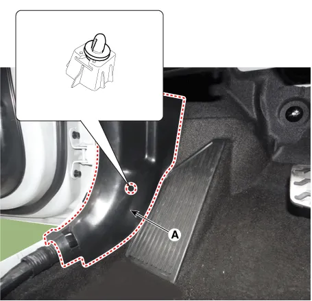
| 7. | Remove the passenger compartment junction box cover (A).
|

| 8. | Separate the crash pad lower panel (A) after loosening the bolts and screws.
|
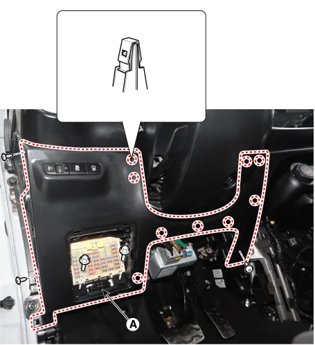
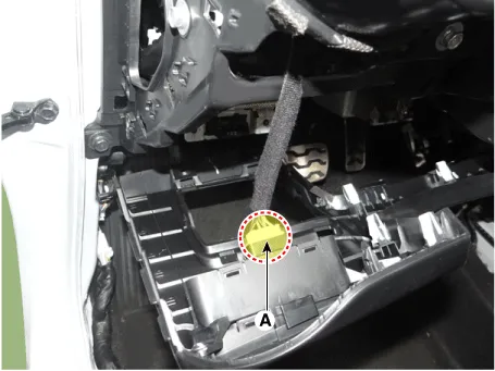
| 9. | Disconnect the crash pad lower side switch connector (A).
|
| 10. | Remove the cluster fascia panel (A) by using a remover.
|

| 11. | Remove the center fascia garnish (A) by using a remover.
|

| 12. | Remove the center fascia panel (A) by using a remover.
|
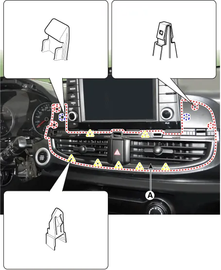
| 13. | Remove the center fascia panel (B) after disconnecting the hazard switch connector (A).
|

| 14. | Remove the crash pad side cover [RH] (A) by using a remover.
|

| 15. | Remove the glove box stopper (A) from the crash pad.
|

| 16. | Remove the glove box (A).
|

| 17. | Remove the crash pad center lower panel (A) after loosening the screws.
|

| 18. | Install in the reverse order of removal.
|
Components and components location Component Location 1. Steering column shroud upper panel 2. Steering column shroud lower panel Repair procedures Replacement Put on gloves to protect your hands.
Components and components location Component Location 1. Crash pad center lower panel Repair procedures Replacement Put on gloves to protect your hands.
Other information:
Kia Picanto (JA) 2017-2026 Service & Repair Manual: Indicators And Gauges
Troubleshooting Troubleshooting Error Item Failure symptom Inspection items Detailed inspections Relevant Parts/ Components Screen display LCD scree
Kia Picanto (JA) 2017-2026 Service & Repair Manual: Seat Heater
Components and components location Component Location 1. Seat heater unit 2. Front seat back heater 3. Front seat cushion heater Schematic diagrams Circuit Diagram Repair procedures Inspection 1.Check for continuity and measure the resistance between terminals No 1 and No 4.
Categories
- Manuals Home
- Kia Picanto Owners Manual
- Kia Picanto Service Manual
- Engine Mechanical System
- Normal Condition
- Suspension System
- New on site
- Most important about car
