Kia Picanto (JA): Cooling System / Cooling Fan
Components and components location
| Components |

| 1. Cooling fan 3. Cooling fan motor | 3. Cooling fan shroud |
Specifications
| Specifications |
|
Item
|
Specification
|
| Fan type | Puller |
| Fan speed control | ON - OFF |
| Air flow rate [㎥/h] | 1,570 - 8% min. |
| Fan speed (rpm) | 1,960 ± 8% |
| Current (A) | 10.0 + 10% max. |
Description and operation
| Description |
Schematic diagrams
| Circuit Diagram |

Repair procedures
| Removal and Installation |
| 1. | Remove the radiator.
(Refer to Cooling System - "Radiator")
|
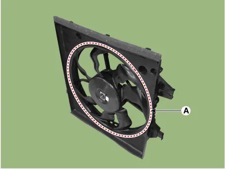
| 2. | Remove the cooling fan assembly (A) from the radiator.
|

| 3. | Install in the reverse order of removal. |
| Disassembly |
| 1. | Remove the cooling fan (A) from the cooling fan assembly.
|
| 2. | Remove the fan motor (A) from the cooling fan shroud.
|


| 3. | Assemble in the reverse order of disassembly. |
| Inspection |
| 1. | Disconnect the fan motor connector. |
| 2. | Connect the battery voltage to the "+" terminal and ground to "-" terminal. |
| 3. | Check the cooling fan motor operates well. |
Components and components location Components 1. Reservoir tank 2. Reservoir hose & pipe 3. Turbo charger water drain hose 4. Water return hose Repair procedures Removal and Installation 1.
Components and components location Components 1. Radiator 2. Radiator upper hose 3. Radiator lower hose 4. Radiator upper mounting bracket 5.
Other information:
Kia Picanto (JA) 2017-2026 Service & Repair Manual: Keyless Entry And Burglar Alarm
Specifications Specification Item Specification Power source 3 V Operating temperature -22 - 167°F (-30 - 75°C) RF Modulation FSK LF Modulation ASK RF frequency 433.92 MHz Button number 3 Function Door lock Door unlock Tailgate unlock Components and components locat
Kia Picanto (JA) 2017-2026 Service & Repair Manual: Power Door Lock Switch
Repair procedures Inspection 1.Check for continuity between the terminals. If there is an abnormality, replace the switch. Removal • When removing with a flat-tip screwdriver or remover, wrap protective tape around the tools to prevent damage to components.
Categories
- Manuals Home
- Kia Picanto Owners Manual
- Kia Picanto Service Manual
- Body Electrical System
- General Information
- Clutch Cable
- New on site
- Most important about car
