Kia Picanto (JA): Clutch System / Clutch Pedal
Components and components location
| Components |

| 1. Clutch pedal assembly | 2. Clutch cable |

| 1. Clutch pedal assembly 2. Ignition lock and clutch switch 3. Master cylinder | 4. Clutch regulator 5. Clutch tube |
Repair procedures
| Replacement |
| 1. | Turn ignition switch OFF and disconnect the negative (-) battery cable. |
| 2. | Loosen the clutch cable adjust nut (A) and then separate the clutch cable
|

| 3. | Remove the crash pad lower panel.
(Refer to Body - "Crash Pad Lower Panel")
|
| 4. | Remove the junction box.
(Refer to Body Electrical System - "Junction Box (Passenger Compartment))
|
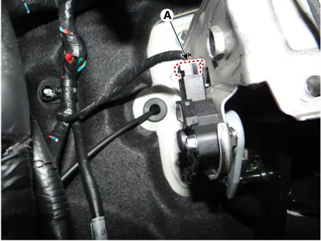
| 5. | Disconnect the cluch switch & ignition lock swtich connector (A).
|
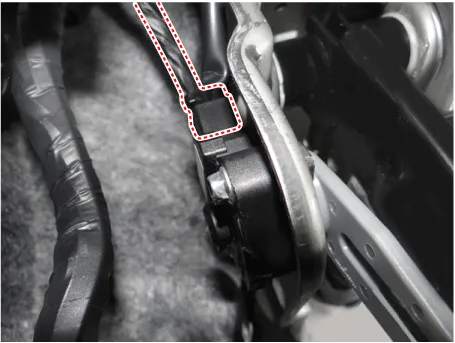
| 6. | Pushing the clutch pedal and then remove the clutch cable (A).
|

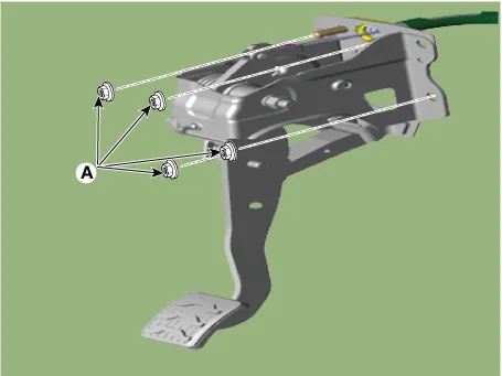
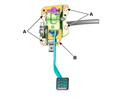
| 7. | Loosen the nuts (A) and then remove the clutch pedal.
|
| 8. | Install in the reverse order of removal. |
| 1. | Turn ignition switch OFF and disconnect the negative (-) battery cable. |
| 2. | Remove the crash pad lower panel.
(Refer to Body - "Crash Pad Lower Panel")
|
| 3. | Remove the junction box.
(Refer to Body Electrical System - "Junction Box (Passenger Compartment))
|
| 4. | Disconnect the ignition lock & clutch switch connector.
|
| 5. | Remove the push rod end (A) from the clutch pedal.
|
| 6. | Remove the battery.
G 1.0 T-GDI KAPPA (Refer to Engine Electrical System - "Battery")
|
| 7. | Remove the ECM.
G 1.0 T-GDI KAPPA (Refer to Engine Control / Fuel System - Engine Control Module (ECM)")
|
| 8. | Disconnect the reservoir hose (A) and clutch tube (B) from the clutch master cylinder after removeing the pin (C).
|

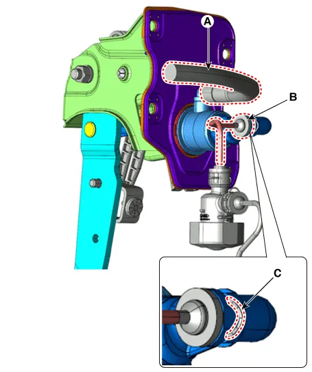
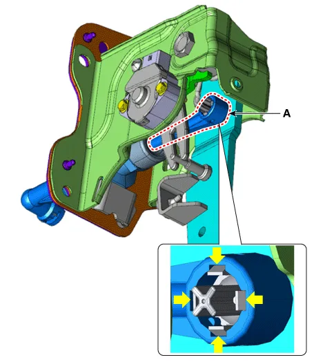
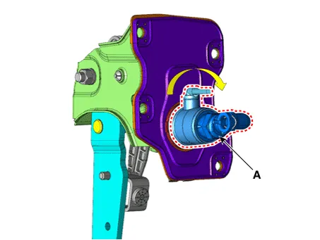
| 9. | Remove the clutch master cylinder (A) by turning it clockwise.
|
| 10. | Remove the clutch pedal (B) after loosening the mounting nuts (A).
|
| 11. | Install in the reverse order of removal. |
Specifications Specifications Item Specifications Working voltage DC 12.5V Operating force Initial position : 0.
Components and components location Components [Kappa 1.0 MPI / FFV, Kappa 1.2 MPI] 1. Clutch pedal assembly 2. Clutch cable Repair procedures Removal 1.
Other information:
Kia Picanto (JA) 2017-2026 Service & Repair Manual: Rear Glass Defogger Printed Heater
Repair procedures Inspection • Wrap tin foil around the end of the voltmeter test lead to prevent damaging the heater line. Apply pressure on the tin foil with hand and move the tin foil along the grid line to check for open circuits.
Kia Picanto (JA) 2017-2026 Service & Repair Manual: Rear Glass Defogger Switch
Repair procedures Inspection 1.In the body electrical system, failure can be quickly diagnosed by using the vehicle diagnostic system (KDS/GDS).The diagnostic system (KDS/GDS) provides the following information.(1)Self diagnosis : Checking failure and code number (DTC)(2) Current data : Checking the system input/output data state (3)Actuation
Categories
- Manuals Home
- Kia Picanto Owners Manual
- Kia Picanto Service Manual
- Thermostat
- Fuel Delivery System
- Power Window Switch
- New on site
- Most important about car
