Kia Picanto (JA): Blower / Climate Control Air Filtar
Description and operation
| Description |
Repair procedures
| Replacement |
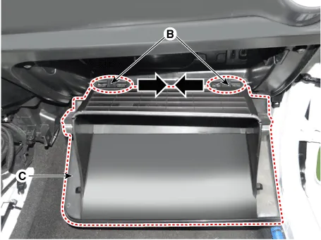
| 1. | Remove the stopper (A) from the glove box.
|

| 2. | Disconnect the pins (B) and then remove the glove box (C).
|
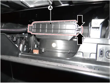
| 3. | Remove the filter cover (A) by pressing the knob.
|
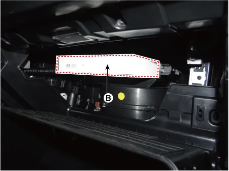
| 4. | Replace
the air filter (B) according to the replacement cycle on the user
manual. When replacing it, mind the direction of the air filter.
|

| 5. | Install in the reverse order of removal. |
Repair procedures Inspection 1.Ignition "ON" 2.Manually operate the control switch and measure the voltage of blower motor. 3.Select the control switch to raise voltage until high speed.
Components and components location Component Location 1. Intake Actuator Description and operation Description 1. The intake actuator is located at the blower unit.
Other information:
Kia Picanto (JA) 2017-2026 Service & Repair Manual: Front Wiper Motor
Components and components location Component Location 1. Cap 2. Nut 3. Wiper arm & blade 4. Cowl top cover 5. Bolt 6. Wiper motor & linkage assembly 7. Wiper motor connector Repair procedures Removal 1.Disconnect the negative (-) battery terminal.
Kia Picanto (JA) 2017-2026 Service & Repair Manual: Blower Resistor (Manual)
Repair procedures Inspection 1.Measure terminal - to - terminal resistance of blower resistor. 2.measured resistance is not within specification, the blower resistor must be replaced. (After removing the resistor) Replacement 1.Disconnect the negative (-) battery terminal.
Categories
- Manuals Home
- Kia Picanto Owners Manual
- Kia Picanto Service Manual
- Cylinder Head
- Automatic Transaxle Fluid
- Suspension System
- New on site
- Most important about car
