Kia Picanto (JA): ISG (Idle Stop & Go) System / Brake switch
Components and components location
| Components |
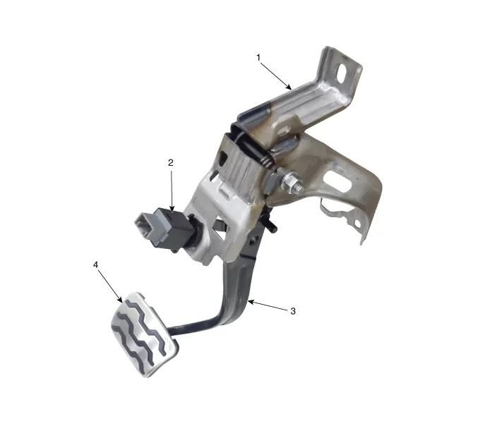
| 1. Brake member assembly 2. Stop lamp switch | 3. Brake pedal arm assembly 4. Brake pedal pad |
Troubleshooting
| Troubleshooting |
| 1. | Part diagnosis
|
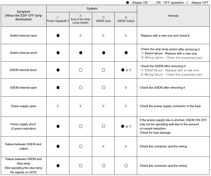
| 2. | Symptom diagnosis
|
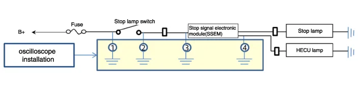
| 3. | Stop lamp switch system diagnosis
SSEM : Stop Signal Electronic Module |
| 4. | Refer to DTC guide when the related DTC codes are displayed. |
Repair procedures
| Removal |
| 1. | Switch "OFF" ignition and disconnect the negative (-) battery terminal. |
| 2. | Remove the crash pad lower panel.
(Refer to Body - "Crash Pad Lower Panel")
|
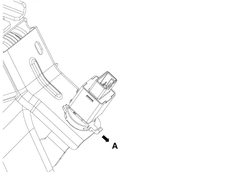
| 3. | Disconnect the stop lamp switch connector (A).
|

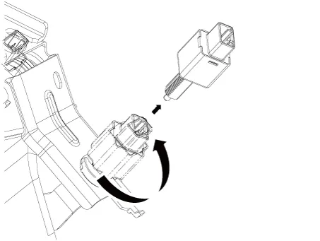
| 4. | Pull the locking plate (A) as indicated by the
|
| 5. | Turn brake switch 45° counterclockwise and remove it.
|
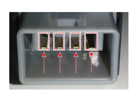
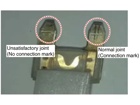
| 6. | Inspect the removed stop lamp switch according to the below procedures.
|
| Installation |
| 1. | Fix the brake pedal arm and insert the brake switch fully until the contact part is invisible.
|

| 2. | After inserting, turn the brake switch 45° clockwise, and then assemble locking plate by pushing it.
|
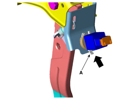
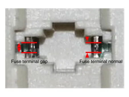
| 3. | Check the gap (A) between brake switch and bracket.
|


| 4. | Install the brake switch connector (A).
|
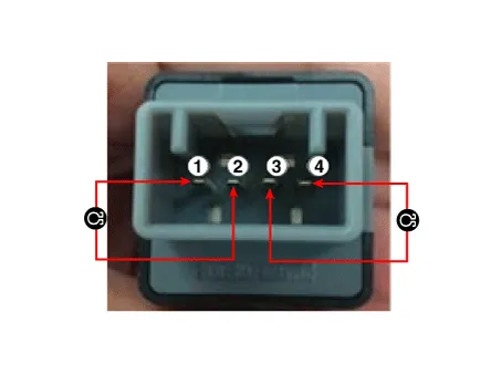
| Inspection |
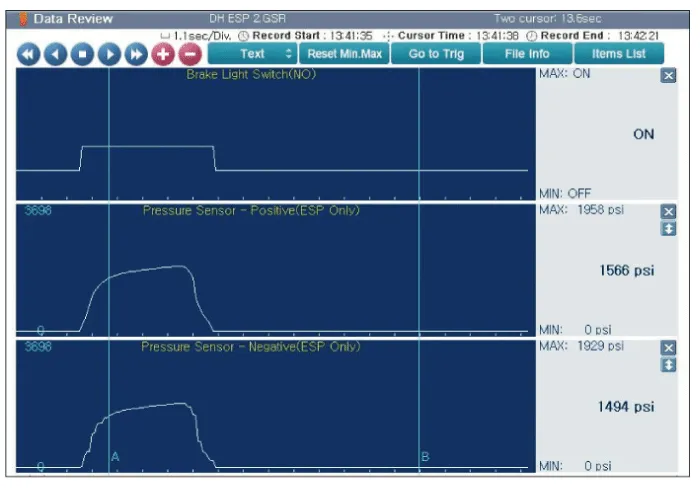
| 1. | Analyze KDS data and confirm if there is anything wrong with the stop lamp switch.
|


Specifications Specification ▷12V, 1.2kW : ISG only Item Specification Rated voltage 12 V, 1.
Description and operation Description Via the seat belt/Door switch, the ISG function can detect that the driver has fastened the seat belt/door.
Other information:
Kia Picanto (JA) 2017-2026 Service & Repair Manual: Mic
Repair procedures Inspection 1.Disconnect the negative (-) battery terminal. 2.Remove the roof trim assembly. (Refer to Body - "Roof Trim Assembly") 3.Remove the hands free mic (A) after loosening the mounting screws. 4.Check tshe continuity of between terminals.
Kia Picanto (JA) 2017-2026 Service & Repair Manual: Start/Stop Button
Components and components location Component Repair procedures Removal 1.Disconnect the negative (-) battery terminal. 2.Remove the crash pad lower panel. (Refer to Body - "Crash Pad Lower Panel") 3.Remove the steering column shroud lower panel.
Categories
- Manuals Home
- Kia Picanto Owners Manual
- Kia Picanto Service Manual
- Timing Chain
- Suspension System
- Thermostat
- New on site
- Most important about car
